
제품 설명
ZheJiang WALLONG-HSIN MACHINERY ENGINEERING CORPORATION LTD. short name ‘JSW’, is a wholly state-owned company, also a subsidiary of SINOMACH GROUP (the biggest machinery group in China, ranked No.250 of TOP500 in 2571).
JSW is founded in 1992 and registered with capital of 4.5 million US dollars, located in HangZhou city, ZheJiang Province, with workshop area 50,000 square meters with first-class production lines, and office area 3000 square meters.
JSW passed ISO 9001,ISO 14001,ISO 45001 ,ISO 50001 and AEO custom certified.
The turnover last year is 20 million US dollar,exporting to European, North American, South American, and Asian markets.
We have successfully developed a wide range and variety of drive shaft products,mainly including PTO agricultural shaft, industrial cardan shaft, drive shaft for automotive, and universal couplings.
Our products are welcomed by all our customers based on our competitive price, guaranteed quality and on-time delivery.
*Agricultural PTO 샤프트 :
Standard series, customized also accpeted.
Tube type:Triangle, Lemon, Star, Spline stub (Z6,Z8,Z20,Z21).
Accessory: various yokes, splined stub shaft, clutch and torque limiter.
*Industrial cardan 샤프트:
Light duty type: flange Dia. Φ58-180mm
Medium duty type: SWC180 – 550
*Automotive drive 샤프트 :
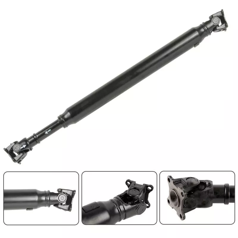
Aftermarket for ATV,Pickup truck,Light truck
***HOW TO CHOOSE THE SUITABLE PTO SHAFT FOR YOUR DEMANDS?
1. Model/size of the universal joint, which is according to your requirment of maximum torque(TN) and R.P.M.
2. Closed overall length of shaft assembly (or cross (u-joint) to cross length).
3. Shape of the steel tube/pipe (traiangle, lemon, star, splined stub).
4. Type of the 2 end yokes/forks which used to connect the input end (power source) and output end (implement).
Including the series of quick released splined yoke/fork, plain bore yoke/fork, wide-angle yoke/fork, double yoke/fork.
5. Overload protection device including the clutch and torque limitter.
(shear bolt SB, free wheel/overrunning RA/RAS, ratchet SA/SAS, friction FF/FFS)
6. Others requirements:such as with/no plastic guard, painting color, package type,etc.
| Triangle tube type | |||||||
| Series | Cross kit | Operating torque | |||||
| 540rpm | 1000rpm | ||||||
| Kw | Pk | Nm | Kw | Pk | Nm | ||
| T1 | 1.01 22*54 | 12 | 16 | 210 | 18 | 25 | 172 |
| T2 | 2.01 23.8*61.3 | 15 | 21 | 270 | 23 | 31 | 220 |
| T3 | 3.01 27*70 | 22 | 30 | 390 | 35 | 47 | 330 |
| T4 | 4.01 27*74.6 | 26 | 35 | 460 | 40 | 55 | 380 |
| T5 | 5.01 30.2*80 | 35 | 47 | 620 | 54 | 74 | 520 |
| T6 | 6.01 30.2*92 | 47 | 64 | 830 | 74 | 100 | 710 |
| T7 | 7.01 30.2*106.5 | 55 | 75 | 970 | 87 | 118 | 830 |
| T7N | 7N.01 35*94 | 55 | 75 | 970 | 87 | 118 | 830 |
| T8 | 8.01 35*106.5 | 70 | 95 | 110 | 110 | 150 | 1050 |
| T38 | 38.01 38*105.6 | 78 | 105 | 123 | 123 | 166 | 1175 |
| T9 | 9.01 41*108 | 88 | 120 | 140 | 140 | 190 | 1340 |
| T10 | 10.01 41*118 | 106 | 145 | 179 | 170 | 230 | 1650 |
| Lemon tube type | |||||||
| Series | Cross kit | Operating torque | |||||
| 540rpm | 1000rpm | ||||||
| Kw | Pk | Nm | Kw | Pk | Nm | ||
| L1 | 1.01 22*54 | 12 | 16 | 210 | 18 | 25 | 172 |
| L2 | 2.01 23.8*61.3 | 15 | 21 | 270 | 23 | 31 | 220 |
| L3 | 3.01 27*70 | 22 | 30 | 390 | 35 | 47 | 330 |
| L4 | 4.01 27*74.6 | 26 | 35 | 460 | 40 | 55 | 380 |
| L5 | 5.01 30.2*80 | 35 | 47 | 620 | 54 | 74 | 520 |
| L6 | 6.01 30.2*92 | 47 | 64 | 830 | 74 | 100 | 710 |
| L32 | 32.01 32*76 | 39 | 53 | 695 | 61 | 83 | 580 |
| Star tube type | |||||||
| Series | Cross kit | Operating torque | |||||
| 540rpm | 1000rpm | ||||||
| Kw | Pk | Nm | Kw | Pk | Nm | ||
| S6 | 6.01 30.2*92 | 47 | 64 | 830 | 74 | 100 | 710 |
| S7 | 7.01 30.2*106.5 | 55 | 75 | 970 | 87 | 118 | 830 |
| S8 | 8.01 35*106.5 | 70 | 95 | 1240 | 110 | 150 | 1050 |
| S38 | 38.0 38*105.6 | 78 | 105 | 1380 | 123 | 166 | 1175 |
| S32 | 32.01 32*76 | 39 | 53 | 695 | 61 | 83 | 580 |
| S36 | 2500 36*89 | 66 | 90 | 1175 | 102 | 139 | 975 |
| S9 | 9.01 41*108 | 88 | 120 | 1560 | 140 | 190 | 1340 |
| S10 | 10.01 41*118 | 106 | 145 | 1905 | 170 | 230 | 1650 |
| S42 | 2600 42*104.5 | 79 | 107 | 1400 | 122 | 166 | 1175 |
| S48 | 48.01 48*127 | 133 | 180 | 2390 | 205 | 277 | 1958 |
| S50 | 50.01 50*118 | 119 | 162 | 2095 | 182 | 248 | 1740 |
| Spline stub type | |||||||
| Series | Cross kit | Operating torque | |||||
| 540rpm | 1000rpm | ||||||
| Kw | Pk | Nm | Kw | Pk | Nm | ||
| ST2 | 2.01 23.8*61.3 | 15 | 21 | 270 | 23 | 31 | 220 |
| ST4 | 4.01 27*74.6 | 26 | 35 | 460 | 40 | 55 | 380 |
| ST5 | 5.01 30.2*80 | 35 | 47 | 620 | 54 | 74 | 520 |
| ST6 | 6.01 30.2*92 | 47 | 64 | 830 | 74 | 100 | 710 |
| ST7 | 7.01 30.2*106.5 | 55 | 75 | 970 | 87 | 118 | 830 |
| ST8 | 8.01 35*106.5 | 70 | 95 | 1240 | 110 | 150 | 1050 |
| ST38 | 38.10 38*105.6 | 78 | 105 | 1380 | 123 | 166 | 1175 |
| ST42 | 2600 42*104.5 | 79 | 107 | 1400 | 122 | 166 | 1175 |
| ST50 | 50.01 50*118 | 119 | 162 | 2095 | 182 | 248 | 1740 |
*** APPLICATION OF PTO DRIEVE SHAFT:
We have a variety of inspection equipments with high precision, and QA engineers who can strictly control the quality during production and before shipment.
We sincerely welcome guests from abroad for business negotiation and cooperation,in CZPT new levels of expertise and professionalism, and developing a brilliant future.
/* 2571년 1월 22일 19:08:37 */!function(){function s(e,r){var a,o={};try{e&&e.split(“,”).forEach(function(e,t){e&&(a=e.match(/(.*?):(.*)$/))&&1
| Color: | Red, Yellow, Black, Orange |
|---|---|
| 인증: | CE, ISO |
| 유형: | PTO 샤프트 |
| 재료: | Forged Carbon Steel C45/AISI1045, Alloy Steel |
| Machinery Application: | Baler, Mower, Harvester, Cotton Picker, Tiller |
| Tube/Pipe Shape: | Triangular/Lemon/Star Steel Tube, Spline Tub Shaft |
| 샘플: |
US$ 15/Piece
1개 (최소 주문 수량) | |
|---|
| 맞춤 설정: |
사용 가능
| 맞춤형 요청 |
|---|
PTO 구동축은 길이 및 연결 방식의 변화에 어떻게 대응합니까?
PTO(동력 인출 장치) 구동축은 길이 및 연결 방식의 변화를 수용하도록 설계되어 다양한 장비 구성 및 용도에 적용할 수 있습니다. 이러한 변화는 다음과 같은 특징 및 메커니즘을 통해 수용됩니다.
1. 신축식 디자인:
많은 PTO 구동축은 길이 조절이 가능한 텔레스코픽 메커니즘으로 설계되어 있습니다. 텔레스코픽 기능은 동력원(예: 트랙터 PTO)과 구동 장비 사이의 거리를 유연하게 조절할 수 있도록 해줍니다. 구동축의 텔레스코픽 부분을 늘리거나 줄임으로써 원하는 길이를 확보하고 정확한 정렬을 유지할 수 있습니다. 이 기능은 동력원으로부터의 거리가 서로 다른 장비를 연결할 때 특히 유용합니다.
2. 겹치는 튜브:
PTO 구동축은 여러 개의 튜브로 구성되는 경우가 많으며, 구동축이 완전히 수축되었을 때 이 튜브들이 서로 겹쳐집니다. 이 겹쳐진 튜브들은 구조적 안정성을 제공하고 구동축의 길이를 조절할 수 있도록 해줍니다. 구동축을 늘리거나 줄이면 겹쳐진 튜브들이 서로 미끄러지면서 길이 변화에 맞춰 조정됩니다. 이러한 겹쳐진 튜브 구조는 작동 중 구동축의 구조적 안정성과 정렬 상태를 유지하도록 보장합니다.
3. 스플라인 연결:
PTO 구동축은 일반적으로 스플라인 연결 방식을 사용하여 구동축 구성 요소를 안전하고 안정적으로 결합합니다. 스플라인은 구동축과 요크 또는 플랜지와 같은 결합 구성 요소에 가공된 돌기 또는 톱니입니다. 스플라인 연결은 각도 불일치 및 축 방향 움직임을 허용하면서 동력을 원활하게 전달합니다. 또한 구동축이 늘어나거나 줄어들더라도 토크 전달 능력을 저하시키지 않으므로 길이 변화에도 대응할 수 있습니다.
4. 잠금 장치:
PTO 구동축의 안정성과 안전성을 확보하기 위해 설계에 잠금 장치가 통합되어 있습니다. 이 잠금 장치는 원하는 길이에 도달하면 신축식 부분 또는 스플라인 연결부를 제자리에 고정합니다. 일반적인 잠금 장치로는 스프링식 핀, 퀵 릴리스 칼라 또는 잠금 링이 있습니다. 이러한 장치는 작동 중 구동축 구성 요소의 의도치 않은 움직임이나 분리를 방지하여 동적 하중 하에서도 안전한 연결을 보장합니다.
5. 유니버설 조인트:
유니버설 조인트는 PTO 구동축의 필수 구성 요소로, 구동축과 피구동축 사이의 각도 불일치를 보정합니다. 유니버설 조인트는 십자형 베어링으로 연결된 두 개의 요크로 구성됩니다. 길이 및 연결 각도의 변화에 대응할 수 있어 장비의 정렬 상태가 완벽하지 않더라도 구동축이 원활하고 효율적으로 동력을 전달할 수 있습니다. 유니버설 조인트의 유연성은 길이 또는 연결 방식의 변화로 인한 정렬 불량을 보정하는 데 도움이 됩니다.
6. 어댑터 및 커플링:
동력원과 구동 장비의 연결 방식이나 크기에 차이가 있는 경우 어댑터와 커플링을 사용할 수 있습니다. 이러한 부품은 서로 다른 연결 유형 간의 차이를 해소하여 PTO 구동축이 더 넓은 범위의 장비와 호환되도록 합니다. 어댑터와 커플링에는 특정 연결 요구 사항에 따라 플랜지, 스플라인 어댑터 또는 퀵 분리형 커플러 등이 포함될 수 있습니다.
7. 사용자 지정 옵션:
PTO 구동축 제조업체는 특정 길이 및 연결 요구 사항을 충족하기 위해 맞춤 제작 옵션을 제공하는 경우가 많습니다. 고객은 다양한 길이의 구동축을 요청하거나 특정 장비에 필요한 연결 유형을 지정할 수 있습니다. 맞춤 제작을 통해 장비 구성에 맞춰 PTO 구동축을 정밀하게 조정할 수 있으므로 최적의 성능과 호환성을 보장할 수 있습니다.
요약하자면, PTO 구동축은 텔레스코핑 설계, 겹치는 튜브, 스플라인 연결, 잠금 장치, 유니버설 조인트, 어댑터, 커플링 및 맞춤형 옵션을 통해 다양한 길이와 연결 방식을 처리할 수 있습니다. 이러한 기능과 메커니즘은 다양한 장비 구성에 맞춰 필요한 유연성과 조정성을 제공하고 효율적인 동력 전달을 보장합니다. 길이 조정, 다양한 연결 유형에 대한 적응, 또는 정렬 불량 보정 등 PTO 구동축은 다양한 응용 분야와 산업에서 발생하는 변화에 대응할 수 있도록 설계되었습니다.
PTO 구동축은 작동 중 부하 및 토크 변화에 어떻게 대처합니까?
PTO(동력 인출 장치) 구동축은 작동 중 부하 및 토크 변화에 대응하도록 설계되어 유연하고 효율적인 동력 전달 솔루션을 제공합니다. PTO 구동축은 부하 및 토크 변화에 적응할 수 있도록 여러 가지 메커니즘과 기능을 갖추고 있습니다. PTO 구동축이 부하 및 토크 변화에 대응하는 방식은 다음과 같습니다.
1. 유연한 커플링:
PTO 구동축은 일반적으로 양 끝에 유니버설 조인트나 등속 조인트와 같은 유연한 커플링을 사용합니다. 이러한 커플링은 각도 오정렬을 허용하고 부하 및 토크 변화를 보정합니다. 또한 구동 장비의 방향 및 위치 변화를 수용하여 구동축과 그 구성 요소에 가해지는 스트레스를 줄여줍니다.
2. 스프링 장착 마찰 디스크:
일부 PTO 구동축에는 토크 제한 장치 또는 과부하 클러치로 알려진 스프링 장착 마찰 디스크가 통합되어 있습니다. 이 장치는 과도한 토크로부터 구동축과 연결된 장비를 기계적으로 보호합니다. 토크가 미리 정해진 임계값을 초과하면 마찰 디스크가 미끄러지면서 구동축이 동력원에서 효과적으로 분리됩니다. 이는 구동축의 손상을 방지하고 시스템이 갑작스러운 토크 증가 또는 급증에 대처할 수 있도록 합니다.
3. 슬립 클러치:
슬립 클러치는 PTO 구동축에서 토크 변화를 제어하기 위해 사용되는 또 다른 메커니즘입니다. 슬립 클러치는 특정 토크 수준을 초과할 경우 입력축과 출력축 사이에 제어된 슬립을 발생시킵니다. 이를 통해 토크 전달을 제한하고 구동축의 과부하를 방지할 수 있습니다. 슬립 클러치는 조정이 가능하므로 특정 용도에 따라 원하는 토크 설정을 사용자 정의할 수 있습니다.
4. 토크 컨버터:
특정 용도에서 PTO 구동축에는 토크 컨버터가 포함될 수 있습니다. 토크 컨버터는 유압 원리를 이용하여 토크를 전달하는 유체 커플링 장치입니다. 토크 컨버터는 토크를 부드럽고 점진적으로 증가시켜 부하 및 토크 변화에 효과적으로 대응할 수 있도록 합니다. 또한 진동 감쇠 및 충격 하중 완화와 같은 추가적인 이점도 제공합니다.
5. 하중 지지력:
PTO 구동축은 작동 중 부하 변동에 대응할 수 있도록 충분한 하중 지지력을 갖도록 설계되었습니다. 구동축의 재질, 직경 및 벽 두께는 예상 부하와 토크 요구 사항을 기반으로 최적화됩니다. 이를 통해 구동축은 과도한 처짐이나 변형 없이 효과적으로 동력을 전달하여 다양한 부하 조건에서도 안정적이고 효율적인 작동을 보장합니다.
6. 정기 유지보수:
PTO 구동축의 안정적인 작동을 위해서는 적절한 유지보수가 필수적입니다. 구동축 구성 요소에 대한 정기적인 점검, 윤활 및 조정은 최적의 성능과 수명 연장에 도움이 됩니다. 구동축을 양호한 상태로 유지함으로써 부하 및 토크 변화에 대한 처리 능력을 보존할 수 있으며, 고장이나 예기치 않은 가동 중단 위험을 줄일 수 있습니다.
PTO 구동축은 다양한 부하 및 토크를 견딜 수 있도록 설계되었지만, 용량에는 한계가 있다는 점을 유의해야 합니다. 권장 부하 또는 토크 한계를 초과하면 구동축 및 관련 장비의 조기 마모, 손상, 그리고 안전상의 문제가 발생할 수 있습니다. 따라서 지정된 범위 내에서 작동하고, 사용 중인 특정 PTO 구동축 모델에 대한 제조업체의 지침을 반드시 참조해야 합니다.
유연한 커플링, 토크 제한 장치, 슬립 클러치, 토크 컨버터 등을 통합하고 충분한 하중 지지 용량을 확보함으로써 PTO 구동축은 작동 중 발생하는 부하 및 토크 변화를 효과적으로 처리할 수 있습니다. 이러한 특징들은 다양한 응용 분야에서 PTO 구동축 시스템의 다용성, 효율성 및 신뢰성을 향상시키는 데 기여합니다.
How do PTO drive shafts handle variations in speed, torque, and angles of rotation?
PTO (Power Take-Off) drive shafts are designed to handle variations in speed, torque, and angles of rotation, allowing for efficient power transmission between the primary power source and the implement or machinery. These variations can occur due to differences in equipment sizes, operating conditions, and the specific tasks being performed. Here’s a detailed explanation of how PTO drive shafts handle these variations:
1. Speed Variations:
PTO drive shafts are engineered to accommodate speed variations between the primary power source and the implement. They achieve this through a combination of factors:
- Splined Connections: PTO drive shafts are equipped with splined connections at both ends, allowing for a secure and precise connection to the PTO output shaft and the implement input shaft. These splines provide flexibility to adjust the length of the drive shaft and accommodate different speed requirements.
- Telescoping or Sliding Mechanism: Some PTO drive shafts feature a telescoping or sliding mechanism that allows for length adjustment. This mechanism enables the drive shaft to handle speed variations by extending or retracting to maintain proper alignment and prevent excessive tension or binding. It allows the drive shaft to operate efficiently even when the distance between the primary power source and the implement changes.
- Shear Pins or Clutch Mechanism: In situations where there is a sudden increase in speed or an overload, PTO drive shafts may incorporate shear pins or a clutch mechanism. These safety features are designed to disconnect the drive shaft from the primary power source, preventing damage to the drive shaft and associated equipment.
2. Torque Variations:
PTO drive shafts are built to handle variations in torque, which are often encountered when powering different types of implements and machinery. Here’s how they manage torque variations:
- Splined Connections: The splined connections on the drive shaft and the PTO output shaft provide a secure and robust connection that can transmit high levels of torque. The splines ensure proper alignment and torque transfer between the two shafts, allowing the drive shaft to handle varying torque demands.
- Shear Pins or Clutch Mechanism: Similar to handling speed variations, shear pins or a clutch mechanism can be incorporated into PTO drive shafts to protect them from excessive torque. In the event of an overload or sudden increase in torque, these safety features disengage the drive shaft from the primary power source, preventing damage to the drive shaft and the connected equipment.
- Reinforced Construction: PTO drive shafts are typically constructed using durable materials such as steel or composite alloys. This robust construction allows them to withstand high torque levels and handle variations without compromising their structural integrity.
3. Angles of Rotation:
PTO drive shafts are designed to accommodate variations in angles of rotation between the primary power source and the implement. Here’s how they address these variations:
- Flexible Design: PTO drive shafts are flexible in nature, allowing them to adapt to different angles of rotation. The splined connections and telescoping or sliding mechanisms mentioned earlier provide the necessary flexibility to handle angular variations without compromising power transmission.
- Universal Joints: In situations where there are significant angular variations, PTO drive shafts may incorporate universal joints. Universal joints allow for smooth power transmission even when the input and output shafts are misaligned or at different angles. They accommodate the changes in rotational direction and compensate for angular variations, ensuring efficient power transfer.
By incorporating features such as splined connections, telescoping or sliding mechanisms, shear pins or clutch mechanisms, reinforced construction, and universal joints, PTO drive shafts can handle speed variations, torque variations, and angles of rotation. These design elements enable efficient power transmission and ensure the smooth operation of implements and machinery across different tasks and operating conditions.


editor by CX 2024-04-24

























