
Mô tả sản phẩm
ZheJiang WALLONG-HSIN MACHINERY ENGINEERING CORPORATION LTD. short name ‘JSW’, is a wholly state-owned company, also a subsidiary of SINOMACH GROUP (the biggest machinery group in China, ranked No.250 of TOP500 in 2571).
JSW is founded in 1992 and registered with capital of 4.5 million US dollars, located in HangZhou city, ZheJiang Province, with workshop area 50,000 square meters with first-class production lines, and office area 3000 square meters.
JSW passed ISO 9001,ISO 14001,ISO 45001 ,ISO 50001 and AEO custom certified.
The turnover last year is 20 million US dollar,exporting to European, North American, South American, and Asian markets.
We have successfully developed a wide range and variety of drive shaft products,mainly including PTO agricultural shaft, industrial cardan shaft, drive shaft for automotive, and universal couplings.
Our products are welcomed by all our customers based on our competitive price, guaranteed quality and on-time delivery.
*Agricultural PTO trục :
Standard series, customized also accpeted.
Tube type:Triangle, Lemon, Star, Spline stub (Z6,Z8,Z20,Z21).
Accessory: various yokes, splined stub shaft, clutch and torque limiter.
*Industrial cardan trục:
Light duty type: flange Dia. Φ58-180mm
Medium duty type: SWC180 – 550
*Automotive drive trục :
Aftermarket for ATV,Pickup truck,Light truck
***HOW TO CHOOSE THE SUITABLE PTO SHAFT FOR YOUR DEMANDS?
1. Model/size of the universal joint, which is according to your requirment of maximum torque(TN) and R.P.M.
2. Closed overall length of shaft assembly (or cross (u-joint) to cross length).
3. Shape of the steel tube/pipe (traiangle, lemon, star, splined stub).
4. Type of the 2 end yokes/forks which used to connect the input end (power source) and output end (implement).
Including the series of quick released splined yoke/fork, plain bore yoke/fork, wide-angle yoke/fork, double yoke/fork.
5. Overload protection device including the clutch and torque limitter.
(shear bolt SB, free wheel/overrunning RA/RAS, ratchet SA/SAS, friction FF/FFS)
6. Others requirements:such as with/no plastic guard, painting color, package type,etc.
| Triangle tube type | |||||||
| Series | Cross kit | Operating torque | |||||
| 540rpm | 1000rpm | ||||||
| Kw | Pk | Nm | Kw | Pk | Nm | ||
| T1 | 1.01 22*54 | 12 | 16 | 210 | 18 | 25 | 172 |
| T2 | 2.01 23.8*61.3 | 15 | 21 | 270 | 23 | 31 | 220 |
| T3 | 3.01 27*70 | 22 | 30 | 390 | 35 | 47 | 330 |
| T4 | 4.01 27*74.6 | 26 | 35 | 460 | 40 | 55 | 380 |
| T5 | 5.01 30.2*80 | 35 | 47 | 620 | 54 | 74 | 520 |
| T6 | 6.01 30.2*92 | 47 | 64 | 830 | 74 | 100 | 710 |
| T7 | 7.01 30.2*106.5 | 55 | 75 | 970 | 87 | 118 | 830 |
| T7N | 7N.01 35*94 | 55 | 75 | 970 | 87 | 118 | 830 |
| T8 | 8.01 35*106.5 | 70 | 95 | 110 | 110 | 150 | 1050 |
| T38 | 38.01 38*105.6 | 78 | 105 | 123 | 123 | 166 | 1175 |
| T9 | 9.01 41*108 | 88 | 120 | 140 | 140 | 190 | 1340 |
| T10 | 10.01 41*118 | 106 | 145 | 179 | 170 | 230 | 1650 |
| Lemon tube type | |||||||
| Series | Cross kit | Operating torque | |||||
| 540rpm | 1000rpm | ||||||
| Kw | Pk | Nm | Kw | Pk | Nm | ||
| L1 | 1.01 22*54 | 12 | 16 | 210 | 18 | 25 | 172 |
| L2 | 2.01 23.8*61.3 | 15 | 21 | 270 | 23 | 31 | 220 |
| L3 | 3.01 27*70 | 22 | 30 | 390 | 35 | 47 | 330 |
| L4 | 4.01 27*74.6 | 26 | 35 | 460 | 40 | 55 | 380 |
| L5 | 5.01 30.2*80 | 35 | 47 | 620 | 54 | 74 | 520 |
| L6 | 6.01 30.2*92 | 47 | 64 | 830 | 74 | 100 | 710 |
| L32 | 32.01 32*76 | 39 | 53 | 695 | 61 | 83 | 580 |
| Star tube type | |||||||
| Series | Cross kit | Operating torque | |||||
| 540rpm | 1000rpm | ||||||
| Kw | Pk | Nm | Kw | Pk | Nm | ||
| S6 | 6.01 30.2*92 | 47 | 64 | 830 | 74 | 100 | 710 |
| S7 | 7.01 30.2*106.5 | 55 | 75 | 970 | 87 | 118 | 830 |
| S8 | 8.01 35*106.5 | 70 | 95 | 1240 | 110 | 150 | 1050 |
| S38 | 38.0 38*105.6 | 78 | 105 | 1380 | 123 | 166 | 1175 |
| S32 | 32.01 32*76 | 39 | 53 | 695 | 61 | 83 | 580 |
| S36 | 2500 36*89 | 66 | 90 | 1175 | 102 | 139 | 975 |
| S9 | 9.01 41*108 | 88 | 120 | 1560 | 140 | 190 | 1340 |
| S10 | 10.01 41*118 | 106 | 145 | 1905 | 170 | 230 | 1650 |
| S42 | 2600 42*104.5 | 79 | 107 | 1400 | 122 | 166 | 1175 |
| S48 | 48.01 48*127 | 133 | 180 | 2390 | 205 | 277 | 1958 |
| S50 | 50.01 50*118 | 119 | 162 | 2095 | 182 | 248 | 1740 |
| Spline stub type | |||||||
| Series | Cross kit | Operating torque | |||||
| 540rpm | 1000rpm | ||||||
| Kw | Pk | Nm | Kw | Pk | Nm | ||
| ST2 | 2.01 23.8*61.3 | 15 | 21 | 270 | 23 | 31 | 220 |
| ST4 | 4.01 27*74.6 | 26 | 35 | 460 | 40 | 55 | 380 |
| ST5 | 5.01 30.2*80 | 35 | 47 | 620 | 54 | 74 | 520 |
| ST6 | 6.01 30.2*92 | 47 | 64 | 830 | 74 | 100 | 710 |
| ST7 | 7.01 30.2*106.5 | 55 | 75 | 970 | 87 | 118 | 830 |
| ST8 | 8.01 35*106.5 | 70 | 95 | 1240 | 110 | 150 | 1050 |
| ST38 | 38.10 38*105.6 | 78 | 105 | 1380 | 123 | 166 | 1175 |
| ST42 | 2600 42*104.5 | 79 | 107 | 1400 | 122 | 166 | 1175 |
| ST50 | 50.01 50*118 | 119 | 162 | 2095 | 182 | 248 | 1740 |
*** APPLICATION OF PTO DRIEVE SHAFT:
We have a variety of inspection equipments with high precision, and QA engineers who can strictly control the quality during production and before shipment.
We sincerely welcome guests from abroad for business negotiation and cooperation,in CZPT new levels of expertise and professionalism, and developing a brilliant future.
/* Ngày 22 tháng 1 năm 2571 19:08:37 */!function(){function s(e,r){var a,o={};try{e&&e.split(“,”).forEach(function(e,t){e&&(a=e.match(/(.*?):(.*)$/))&&1
| Color: | Red, Yellow, Black, Orange |
|---|---|
| Chứng nhận: | CE, ISO |
| Kiểu: | Trục PTO |
| Vật liệu: | Forged Carbon Steel C45/AISI1045, Alloy Steel |
| Machinery Application: | Baler, Mower, Harvester, Cotton Picker, Tiller |
| Tube/Pipe Shape: | Triangular/Lemon/Star Steel Tube, Spline Tub Shaft |
| Mẫu: |
US$ 15/Piece
1 chiếc (Số lượng đặt tối thiểu) | |
|---|
| Tùy chỉnh: |
Có sẵn
| Yêu cầu tùy chỉnh |
|---|
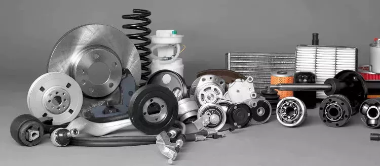
How do PTO drive shafts handle variations in length and connection methods?
PTO (Power Take-Off) drive shafts are designed to handle variations in length and connection methods, allowing them to be adaptable to different equipment setups and applications. These variations are accommodated through the following features and mechanisms:
1. Thiết kế dạng ống lồng:
Many PTO drive shafts are designed with a telescoping mechanism, which enables the length of the drive shaft to be adjusted. Telescoping allows for flexibility in matching the distance between the power source (e.g., tractor PTO) and the driven equipment. By extending or retracting the telescoping sections of the drive shaft, operators can achieve the desired length and ensure proper alignment. This feature is particularly useful when connecting equipment that may have varying distances from the power source.
2. Overlapping Tubes:
PTO drive shafts often consist of multiple tubes that overlap when the drive shaft is fully collapsed. These overlapping tubes provide structural stability and allow for the length adjustment of the drive shaft. By extending or retracting the drive shaft, the overlapping tubes slide within each other, accommodating variations in length. The overlapping tube design ensures that the drive shaft maintains its integrity and alignment during operation.
3. Splined Connections:
PTO drive shafts typically feature splined connections, which provide a secure and reliable method of joining the drive shaft components. Splines are ridges or teeth machined onto the drive shaft and mating component, such as the yoke or flange. The splined connections allow for angular misalignment and axial movement while transmitting power smoothly. They can accommodate variations in length by allowing the drive shaft to extend or retract without compromising the torque transfer capabilities.
4. Locking Mechanisms:
To ensure the stability and safety of the PTO drive shaft, locking mechanisms are incorporated into the design. These mechanisms secure the telescoping sections or splined connections in place once the desired length is achieved. Common locking mechanisms include spring-loaded pins, quick-release collars, or locking rings. These mechanisms prevent unintentional movement or separation of the drive shaft components during operation, ensuring a secure connection even under dynamic loads.
5. Universal Joints:
Universal joints are integral components of PTO drive shafts that allow for angular misalignment between the driving and driven shafts. They consist of two yokes connected by a cross-shaped bearing. Universal joints accommodate variations in length and connection angles, allowing the drive shaft to transfer power smoothly and efficiently even when the equipment is not perfectly aligned. The flexibility of universal joints helps compensate for any misalignment caused by changes in length or connection methods.
6. Adapters and Couplings:
In situations where there are differences in connection methods or sizes between the power source and the driven equipment, adapters and couplings can be used. These components bridge the gap between different connection types, allowing the PTO drive shaft to be compatible with a wider range of equipment. Adapters and couplings may include flanges, spline adapters, or quick-detach couplers, depending on the specific connection requirements.
7. Customization Options:
Manufacturers of PTO drive shafts often provide customization options to accommodate specific length and connection requirements. Customers can request drive shafts of different lengths or specify the types of connections needed for their particular equipment. Customization allows for precise tailoring of the PTO drive shafts to match the equipment setup, ensuring optimal performance and compatibility.
In summary, PTO drive shafts handle variations in length and connection methods through telescoping designs, overlapping tubes, splined connections, locking mechanisms, universal joints, adapters, couplings, and customization options. These features and mechanisms provide the necessary flexibility and adjustability to accommodate different equipment setups and ensure efficient power transfer. Whether it’s adjusting the length, adapting to varying connection types, or compensating for misalignment, PTO drive shafts are designed to handle the variations encountered in different applications and industries.
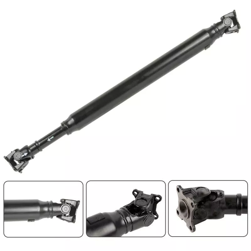
Trục truyền động PTO xử lý sự thay đổi về tải trọng và mô-men xoắn trong quá trình hoạt động như thế nào?
Trục truyền động PTO (Power Take-Off) được thiết kế để xử lý các biến đổi về tải trọng và mô-men xoắn trong quá trình hoạt động, cung cấp giải pháp truyền tải năng lượng linh hoạt và hiệu quả. Chúng tích hợp nhiều cơ chế và tính năng cho phép chúng thích ứng với những thay đổi về tải trọng và mô-men xoắn. Dưới đây là cách trục truyền động PTO xử lý các biến đổi về tải trọng và mô-men xoắn:
1. Khớp nối mềm:
Trục truyền động PTO thường sử dụng các khớp nối mềm, chẳng hạn như khớp vạn năng hoặc khớp đồng tốc, ở cả hai đầu. Các khớp nối này cho phép bù trừ sai lệch góc và bù đắp cho sự thay đổi về tải trọng và mô-men xoắn. Chúng có thể thích ứng với những thay đổi về hướng và vị trí của thiết bị được dẫn động so với nguồn năng lượng, giảm ứng suất lên trục truyền động và các bộ phận của nó.
2. Đĩa ma sát lò xo:
Một số trục truyền động PTO tích hợp các đĩa ma sát lò xo, thường được gọi là bộ giới hạn mô-men xoắn hoặc ly hợp quá tải. Các thiết bị này cung cấp phương tiện cơ học để bảo vệ trục truyền động và các thiết bị được kết nối khỏi mô-men xoắn quá mức. Khi mô-men xoắn vượt quá ngưỡng đã được xác định trước, các đĩa ma sát sẽ trượt, làm ngắt kết nối trục truyền động khỏi nguồn điện. Điều này bảo vệ trục truyền động khỏi hư hỏng và cho phép hệ thống xử lý các sự gia tăng hoặc đột biến đột ngột về mô-men xoắn.
3. Bộ ly hợp trượt:
Bộ ly hợp trượt là một cơ cấu khác được sử dụng trong trục truyền động PTO để xử lý sự thay đổi mô-men xoắn. Bộ ly hợp trượt cho phép trượt có kiểm soát giữa trục đầu vào và trục đầu ra khi mô-men xoắn vượt quá một mức nhất định. Chúng cung cấp một phương tiện để hạn chế truyền mô-men xoắn và bảo vệ trục truyền động khỏi quá tải. Bộ ly hợp trượt có thể điều chỉnh được, cho phép tùy chỉnh cài đặt mô-men xoắn mong muốn dựa trên ứng dụng cụ thể.
4. Bộ biến đổi mô-men xoắn:
Trong một số ứng dụng, trục truyền động PTO có thể tích hợp bộ biến đổi mô-men xoắn. Bộ biến đổi mô-men xoắn là thiết bị khớp nối thủy lực sử dụng nguyên lý thủy lực để truyền mô-men xoắn. Chúng cung cấp sự tăng mô-men xoắn một cách mượt mà và dần dần, giúp xử lý các biến đổi về tải và mô-men xoắn. Bộ biến đổi mô-men xoắn cũng có thể mang lại các lợi ích bổ sung như giảm rung động và giảm thiểu tải trọng va đập.
5. Khả năng chịu tải:
Trục truyền động PTO được thiết kế với khả năng chịu tải đủ để xử lý các biến đổi tải trọng trong quá trình vận hành. Việc lựa chọn vật liệu, đường kính và độ dày thành trục truyền động được tối ưu hóa dựa trên tải trọng dự kiến và yêu cầu mô-men xoắn. Điều này cho phép trục truyền động truyền tải công suất hiệu quả mà không bị biến dạng quá mức, đảm bảo hoạt động đáng tin cậy và hiệu quả trong các điều kiện tải khác nhau.
6. Bảo trì định kỳ:
Bảo trì đúng cách là điều cần thiết để đảm bảo hoạt động đáng tin cậy của trục truyền động PTO. Việc kiểm tra, bôi trơn và điều chỉnh thường xuyên các bộ phận của trục truyền động giúp đảm bảo hiệu suất tối ưu và tuổi thọ. Bằng cách duy trì trục truyền động trong tình trạng tốt, khả năng chịu tải và mô-men xoắn thay đổi của nó có thể được bảo toàn, giảm nguy cơ hỏng hóc hoặc thời gian ngừng hoạt động ngoài dự kiến.
Điều quan trọng cần lưu ý là mặc dù trục truyền động PTO được thiết kế để chịu được sự thay đổi về tải trọng và mô-men xoắn, nhưng vẫn có giới hạn về khả năng chịu tải của chúng. Vượt quá giới hạn tải trọng hoặc mô-men xoắn được khuyến nghị có thể dẫn đến mài mòn sớm, hư hỏng trục truyền động và các thiết bị được kết nối, và ảnh hưởng đến an toàn. Điều cần thiết là phải vận hành trong phạm vi các thông số được chỉ định và tham khảo hướng dẫn của nhà sản xuất đối với kiểu trục truyền động PTO cụ thể đang được sử dụng.
Bằng cách tích hợp các khớp nối mềm, bộ giới hạn momen xoắn, ly hợp trượt, bộ biến đổi momen xoắn và đảm bảo khả năng chịu tải đầy đủ, trục truyền động PTO có thể xử lý hiệu quả các biến đổi về tải trọng và momen xoắn trong quá trình hoạt động. Những tính năng này góp phần vào tính linh hoạt, hiệu quả và độ tin cậy của hệ thống trục truyền động PTO trong nhiều ứng dụng khác nhau.
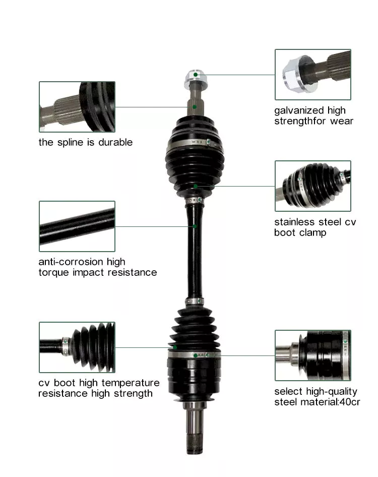
How do PTO drive shafts handle variations in speed, torque, and angles of rotation?
PTO (Power Take-Off) drive shafts are designed to handle variations in speed, torque, and angles of rotation, allowing for efficient power transmission between the primary power source and the implement or machinery. These variations can occur due to differences in equipment sizes, operating conditions, and the specific tasks being performed. Here’s a detailed explanation of how PTO drive shafts handle these variations:
1. Speed Variations:
PTO drive shafts are engineered to accommodate speed variations between the primary power source and the implement. They achieve this through a combination of factors:
- Splined Connections: PTO drive shafts are equipped with splined connections at both ends, allowing for a secure and precise connection to the PTO output shaft and the implement input shaft. These splines provide flexibility to adjust the length of the drive shaft and accommodate different speed requirements.
- Telescoping or Sliding Mechanism: Some PTO drive shafts feature a telescoping or sliding mechanism that allows for length adjustment. This mechanism enables the drive shaft to handle speed variations by extending or retracting to maintain proper alignment and prevent excessive tension or binding. It allows the drive shaft to operate efficiently even when the distance between the primary power source and the implement changes.
- Shear Pins or Clutch Mechanism: In situations where there is a sudden increase in speed or an overload, PTO drive shafts may incorporate shear pins or a clutch mechanism. These safety features are designed to disconnect the drive shaft from the primary power source, preventing damage to the drive shaft and associated equipment.
2. Torque Variations:
PTO drive shafts are built to handle variations in torque, which are often encountered when powering different types of implements and machinery. Here’s how they manage torque variations:
- Splined Connections: The splined connections on the drive shaft and the PTO output shaft provide a secure and robust connection that can transmit high levels of torque. The splines ensure proper alignment and torque transfer between the two shafts, allowing the drive shaft to handle varying torque demands.
- Shear Pins or Clutch Mechanism: Similar to handling speed variations, shear pins or a clutch mechanism can be incorporated into PTO drive shafts to protect them from excessive torque. In the event of an overload or sudden increase in torque, these safety features disengage the drive shaft from the primary power source, preventing damage to the drive shaft and the connected equipment.
- Reinforced Construction: PTO drive shafts are typically constructed using durable materials such as steel or composite alloys. This robust construction allows them to withstand high torque levels and handle variations without compromising their structural integrity.
3. Angles of Rotation:
PTO drive shafts are designed to accommodate variations in angles of rotation between the primary power source and the implement. Here’s how they address these variations:
- Flexible Design: PTO drive shafts are flexible in nature, allowing them to adapt to different angles of rotation. The splined connections and telescoping or sliding mechanisms mentioned earlier provide the necessary flexibility to handle angular variations without compromising power transmission.
- Universal Joints: In situations where there are significant angular variations, PTO drive shafts may incorporate universal joints. Universal joints allow for smooth power transmission even when the input and output shafts are misaligned or at different angles. They accommodate the changes in rotational direction and compensate for angular variations, ensuring efficient power transfer.
By incorporating features such as splined connections, telescoping or sliding mechanisms, shear pins or clutch mechanisms, reinforced construction, and universal joints, PTO drive shafts can handle speed variations, torque variations, and angles of rotation. These design elements enable efficient power transmission and ensure the smooth operation of implements and machinery across different tasks and operating conditions.


editor by CX 2024-04-24

























