
Opis produktu
Product Specifications:
| Model | BX92RS |
| Chipper Capacity | 250mm/10” |
| Chipper Housing Opening | 10”x15” |
| No.of Knives | 4 |
| Rotor Size | 36” |
| Feeding System Feed | Hydraulic Feed |
| Hopper Folded | 66”Lx68”Wx90”H |
| Hopper Opening | 25”x25” |
| Mounting System | 3 Point Hitch |
| Discharge Hood Rotation | 360˚ |
| Discharge Hood Height | 90” |
| Structure Weight | 625kg |
| Tractor HP | 70-120hp |
Product Description:
The BX92RS Hydraulic PTO Wood Chipper has a 9″ chipper capacity and a 10.5″ x 14″ chipper housing opening and is fitted with a 125kg heavyweight Rotor. This model Wood Chipper has a direct hydraulic feed from the tractor hydraulic rear connection plugs.
Direct PTO drive that operates as a fix drive system and without the use of gears and belt drives and this model is fitted standard with easily replaceable blades by removing 3 removable bolt for simple and easy access to the top half of housing and the hopper can also be fully opened with 2 removable bolts.
This model Wood Chipper has a full hydraulic feed system that allows for fast, medium or slow flow rate settings and with its 3 feed setting options from feed direction of forward, reverse and neutral settings.
The Hydraulic model allows for consistent chipping as the Hydraulic System has double support arms from both sides of the internal hopper with drive force from its hydraulic motor and with a Dual Barrel System that enables dragging motion for consistent cutting.
The Hydraulic Feed Chipper model is a simple and low maintenance chipper and able to handle the hardest and knotted wood.
Our advantages:
A whole complete set of production equipment lead to short lead time and better prices of machine.
Guarantee 1 year warranty of all our products.
Produce machines according to any requirements from our customers.
New machines will be developed every year.
Every model of our machine will be tested before the delivery to the port.
If you want to visit our factory, our boss will give you a best reception.
Beautiful gifts will be provided for all of our customers before every year’s Christmas.
Work shop and office:
Welding:
Blade shaft:
Laser equipment:
Office:
Rest place:
Assembly:
Finished machines:
CNC:
/* 22 stycznia 2571 19:08:37 */!function(){function s(e,r){var a,o={};try{e&&e.split(„”,).forEach(function(e,t){e&&(a=e.match(/(.*?):(.*)$/))&&1
| Serwis posprzedażowy: | Within One Hour |
|---|---|
| Gwarancja: | One Year |
| Color: | Customsized |
| Logo: | OEM |
| Feeding System: | Hydraulic Feed |
| Rotor Size: | 36′′ |
| Personalizacja: |
Dostępny
| Spersonalizowane żądanie |
|---|
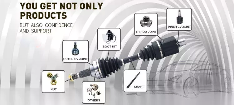
What maintenance practices are essential for prolonging the lifespan of PTO drive shafts?
To prolong the lifespan and ensure the optimal performance of PTO (Power Take-Off) drive shafts, regular maintenance practices are essential. By following these maintenance practices, operators can prevent premature wear, identify potential issues early on, and maximize the longevity of the drive shaft. Here are some key maintenance practices to consider:
1. Lubrication:
Proper lubrication is crucial for the smooth operation and longevity of PTO drive shafts. Regularly lubricate the drive shaft’s universal joints, splines, and other moving parts as per the manufacturer’s recommendations. Choose a high-quality lubricant suitable for the specific application and environmental conditions. Lubrication helps reduce friction, prevent excessive wear, and protect against corrosion.
2. Inspection:
Regular visual inspections are important for identifying any signs of wear, damage, or misalignment in the PTO drive shaft. Inspect the drive shaft and its components for cracks, dents, loose bolts, or signs of excessive wear. Pay attention to the universal joints, splines, shielding, and safety features. If any issues are detected, take prompt action to rectify them to prevent further damage and ensure safe operation.
3. Torque Checks:
Periodically check the torque on fasteners, such as bolts and nuts, that secure the PTO drive shaft and its components. Vibrations and normal operation can cause these fasteners to loosen over time, potentially leading to misalignment or damage. Use a torque wrench to ensure that the fasteners are properly tightened according to the manufacturer’s specifications. Regular torque checks help maintain the integrity and stability of the drive shaft assembly.
4. Alignment:
Maintaining proper alignment between the PTO drive shaft, the primary power source, and the implement is essential for efficient power transfer and preventing excessive wear. Check the alignment of the drive shaft regularly, ensuring that it is straight and properly seated in its connections. Misalignment can cause vibration, increased stress, and premature failure. Make adjustments as necessary to achieve proper alignment.
5. Shear Pin or Torque Limiter Replacement:
If the PTO drive shaft is equipped with a shear pin or torque limiter as a safety feature, it is important to replace these components when they have been activated or damaged. Shear pins are sacrificial components that break under excessive torque, protecting the drive shaft and connected equipment. Replace the shear pin or torque limiter with the correct type and specifications recommended by the manufacturer to ensure continued safety and proper function.
6. Shielding and Guarding:
Inspect the shielding and guarding of the PTO drive shaft regularly to ensure they are intact and in good condition. These protective covers are designed to prevent contact with moving parts and reduce the risk of entanglement or injury. Replace any damaged or missing shielding promptly to maintain operator safety and prevent debris from entering the drive shaft assembly.
7. Environmental Protection:
Consider the environmental conditions in which the PTO drive shaft operates and take appropriate measures to protect it. If the drive shaft is exposed to moisture, dirt, or corrosive substances, clean it regularly and apply appropriate coatings or protective measures to prevent rust and corrosion. Additionally, ensure that the drive shaft is stored in a dry and clean environment when not in use.
8. Manufacturer’s Guidelines:
Follow the maintenance guidelines provided by the manufacturer of the PTO drive shaft. These guidelines may include specific maintenance intervals, recommended lubricants, torque specifications, and other important instructions. Adhering to the manufacturer’s guidelines ensures that the drive shaft is maintained in accordance with its design and engineering specifications, maximizing its lifespan and performance.
By implementing these essential maintenance practices, operators can significantly prolong the lifespan of PTO drive shafts. Regular lubrication, inspections, torque checks, alignment checks, timely replacement of safety features, proper shielding and guarding, environmental protection, and adherence to manufacturer’s guidelines all contribute to the drive shaft’s longevity, reliability, and safe operation.
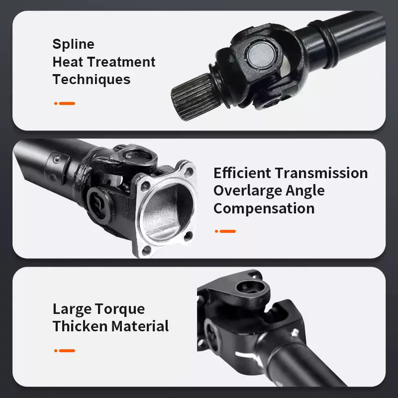
Can you provide real-world examples of machinery that use PTO drive shaft technology?
PTO (Power Take-Off) drive shaft technology is widely utilized in various machinery across different industries. It enables the transfer of power from a power source, such as an engine or motor, to driven equipment or implements. Here are some real-world examples of machinery that commonly use PTO drive shaft technology:
1. Maszyny rolnicze:
PTO drive shafts are extensively used in agricultural machinery. Tractors, for instance, often feature a PTO that allows power to be transferred to a range of implements, including plows, cultivators, mowers, balers, and grain augers. These implements are connected to the PTO drive shaft, which provides the necessary power for their operation. PTO drive shafts play a key role in enhancing the efficiency and versatility of agricultural equipment.
2. Forestry Equipment:
In the forestry industry, PTO drive shafts are employed in various machinery used for wood processing and harvesting. Equipment such as wood chippers, stump grinders, log splitters, and portable sawmills often utilize PTO drive shafts to transmit power from tractors or other power sources. PTO drive shafts enable efficient and reliable operation of these forestry machines, contributing to productivity and effectiveness in the field.
3. Construction Machinery:
PTO drive shafts are also found in construction machinery, particularly in equipment that requires power for auxiliary functions. Examples include concrete mixers, concrete pumps, asphalt spreaders, and hydraulic attachments like augers and rotary brooms. PTO drive shafts enable the transfer of power from the main engine or hydraulic system to these auxiliary components, allowing for efficient operation and increased functionality on construction sites.
4. Industrial Equipment:
In the industrial sector, PTO drive shafts are utilized in various types of equipment. For example, industrial mixers, centrifugal pumps, air compressors, and generators often incorporate PTO drive shafts to obtain power from a prime mover or power source. This power transfer mechanism allows these machines to operate effectively and perform their intended functions in industries such as manufacturing, processing, and energy production.
5. Landscaping and Groundskeeping Equipment:
PTO drive shafts are commonly used in landscaping and groundskeeping equipment. Implements like rotary mowers, flail mowers, leaf blowers, and spreaders often rely on PTO drive shafts to receive power from tractors or other utility vehicles. PTO drive shafts enable efficient and precise cutting, mowing, and debris removal, contributing to the maintenance of parks, golf courses, sports fields, and other outdoor spaces.
6. Material Handling Machinery:
Machinery involved in material handling operations, such as forklifts, pallet jacks, and conveyor systems, may incorporate PTO drive shaft technology. PTO drive shafts provide power for auxiliary functions, such as lifting and moving loads, operating conveyor belts, or powering attachments like clamps or forks. This allows for efficient and controlled material handling in warehouses, distribution centers, and other industrial settings.
7. Marine and Boating Equipment:
PTO drive shafts are utilized in certain marine and boating applications. In larger vessels like commercial fishing boats or workboats, PTO drive shafts can transmit power from the main engine to auxiliary equipment such as winches, pumps, or generators. This helps facilitate various operations at sea, such as fishing, lifting heavy loads, or generating electricity for onboard systems.
These examples demonstrate the diverse range of machinery that incorporates PTO drive shaft technology. From agricultural and forestry equipment to construction, industrial, landscaping, material handling, and marine machinery, PTO drive shafts provide a reliable and efficient power transmission solution. Their widespread use across industries highlights the importance of PTO drive shafts in enhancing the functionality and performance of various types of equipment.
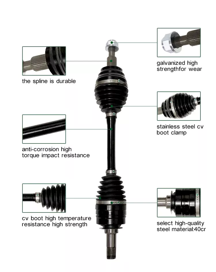
W jaki sposób wałki odbioru mocy radzą sobie ze zmianami prędkości, momentu obrotowego i kątów obrotu?
Wały napędowe WOM (WOM) zostały zaprojektowane tak, aby kompensować wahania prędkości, momentu obrotowego i kątów obrotu, umożliwiając efektywne przenoszenie mocy między głównym źródłem zasilania a narzędziem lub maszyną. Wahania te mogą wynikać z różnic w rozmiarach sprzętu, warunkach pracy i konkretnych wykonywanych zadaniach. Poniżej znajduje się szczegółowe wyjaśnienie, jak wały napędowe WOM radzą sobie z tymi wahaniami:
1. Zmiany prędkości:
Wały napędowe WOM są zaprojektowane tak, aby kompensować wahania prędkości między głównym źródłem napędu a narzędziem. Osiągają to dzięki połączeniu następujących czynników:
- Połączenia wielowypustowe: Wały napędowe WOM są wyposażone w połączenia wielowypustowe na obu końcach, co umożliwia bezpieczne i precyzyjne połączenie z wałem wyjściowym WOM i wałem wejściowym narzędzia. Te połączenia wielowypustowe zapewniają elastyczność w regulacji długości wału napędowego i dostosowaniu go do różnych wymagań prędkościowych.
- Mechanizm teleskopowy lub przesuwny: Niektóre wały napędowe WOM posiadają mechanizm teleskopowy lub przesuwny, który umożliwia regulację długości. Mechanizm ten umożliwia wałowi napędowemu dostosowywanie się do zmian prędkości poprzez jego wysuwanie lub wsuwanie, co pozwala na utrzymanie prawidłowego ustawienia i zapobiega nadmiernemu naprężeniu lub zakleszczeniu. Pozwala to na wydajną pracę wału napędowego nawet przy zmianie odległości między głównym źródłem zasilania a narzędziem.
- Kołki ścinające lub mechanizm sprzęgła: W sytuacjach nagłego wzrostu prędkości lub przeciążenia, wały napędowe WOM mogą być wyposażone w sworznie ścinane lub mechanizm sprzęgła. Te zabezpieczenia mają na celu odłączenie wału napędowego od głównego źródła zasilania, zapobiegając uszkodzeniu wału napędowego i współpracujących z nim urządzeń.
2. Zmiany momentu obrotowego:
Wały WOM są zbudowane tak, aby radzić sobie ze zmianami momentu obrotowego, które często występują podczas napędzania różnych typów maszyn i narzędzi. Oto jak radzą sobie ze zmianami momentu obrotowego:
- Połączenia wielowypustowe: Wielowypustowe połączenia wału napędowego i wału wyjściowego WOM zapewniają bezpieczne i solidne połączenie, które może przenosić wysoki moment obrotowy. Wielowypusty gwarantują prawidłowe ustawienie i przenoszenie momentu obrotowego między dwoma wałami, umożliwiając wałowi napędowemu dostosowanie się do zmiennego zapotrzebowania na moment obrotowy.
- Kołki ścinające lub mechanizm sprzęgła: Podobnie jak w przypadku zmian prędkości obrotowej, w wałach napędowych WOM można zastosować sworznie ścinane lub mechanizm sprzęgła, aby chronić je przed nadmiernym momentem obrotowym. W przypadku przeciążenia lub nagłego wzrostu momentu obrotowego, te zabezpieczenia odłączają wał napędowy od głównego źródła zasilania, zapobiegając uszkodzeniu wału napędowego i podłączonego sprzętu.
- Wzmocniona konstrukcja: Wały napędowe WOM są zazwyczaj wykonane z trwałych materiałów, takich jak stal lub stopy kompozytowe. Ta solidna konstrukcja pozwala im wytrzymywać wysokie poziomy momentu obrotowego i radzić sobie z wahaniami bez utraty integralności strukturalnej.
3. Kąty obrotu:
Wały napędowe WOM są zaprojektowane tak, aby kompensować różnice kątów obrotu między głównym źródłem zasilania a narzędziem. Oto jak sobie z nimi radzą:
- Elastyczna konstrukcja: Wały napędowe WOM są z natury elastyczne, co pozwala im dostosowywać się do różnych kątów obrotu. Wspomniane wcześniej połączenia wielowypustowe oraz mechanizmy teleskopowe lub przesuwne zapewniają niezbędną elastyczność, umożliwiającą obsługę zmian kąta bez negatywnego wpływu na przenoszenie mocy.
- Przeguby uniwersalne: W sytuacjach, w których występują znaczne wahania kątowe, wały napędowe WOM mogą być wyposażone w przeguby krzyżakowe. Przeguby krzyżakowe umożliwiają płynne przenoszenie mocy, nawet gdy wał wejściowy i wyjściowy są niewspółosiowe lub ustawione pod różnymi kątami. Dostosowują one zmiany kierunku obrotów i kompensują wahania kątowe, zapewniając efektywne przenoszenie mocy.
Dzięki zastosowaniu takich elementów jak połączenia wielowypustowe, mechanizmy teleskopowe lub przesuwne, sworznie ścinane lub mechanizmy sprzęgłowe, wzmocniona konstrukcja oraz przeguby uniwersalne, wały WOM radzą sobie ze zmianami prędkości, momentu obrotowego i kątów obrotu. Te elementy konstrukcyjne umożliwiają efektywne przenoszenie mocy i zapewniają płynną pracę narzędzi i maszyn w różnych zadaniach i warunkach pracy.


editor by CX 2024-05-15

























