
Descrizione del prodotto
1.P roduct Description
Thi s Gear shaft, Herringbone Gear Shaft, Bevel Gear, Eccentric Shaft mainly used on vessel engine, fan internal gear
2.1. Gear Shaft Processing
Gear Shaft drawing CHECK, Make Forging Mold, Forging Mold Quality Inspection Check, Machine Processing, Check Size\Hardness\Surface Finish and other technical parameters on drawing.
2.2. Herringbone Gear Shaft Package
Spray anti-rust oil on Herringbone Gear Shaft, Wrap waterproof cloth around Gear Shaft for reducer, Prepare package by shaft shape&weight to choose steel frame, steel support or wooden box etc.
2.3. OEM Customized Gear Shaft
We supply OEM SERVICE, customized herringbone gear shaft with big module, more than 1tons big weight, more than 3m length, 42CrMo/35CrMo or your specified required material gear shaft.
2.Product Technical info.
| Module | m | Range: 5~70 |
| Gear Teeth Number | z | OEM by drawing’s technical parameters |
| Teeth Height | H | OEM by drawing’s technical parameters |
| Teeth Thickness | S | OEM by drawing’s technical parameters |
| Tooth pitch | P | OEM by drawing’s technical parameters |
| Tooth addendum | Ha | OEM by drawing’s technical parameters |
| Tooth dedendum | Hf | OEM by drawing’s technical parameters |
| Working height | h’ | OEM by drawing’s technical parameters |
| Bottom clearance | C | OEM by drawing’s technical parameters |
| Pressure Angle | α | OEM by drawing’s technical parameters |
| Helix Angle, | OEM by drawing’s technical parameters | |
| Surface hardness | HRC | Range: HRC 50~HRC63(Quenching) |
| Durezza: | HB | Range: HB150~HB280; Hardening Tempering/ Hardened Tooth Surface |
| Surface finish | Range: Ra1.6~Ra3.2 | |
| Tooth surface roughness | Ra | Range: ≥0.4 |
| Gear Accuracy Grade | Grade Range: 5-6-7-8-9 (ISO 1328) | |
| Lunghezza | L | Range: 0.8m~10m |
| Weight | Kg | Range: Min. 100kg~Max. 80tons Single Piece |
| Gear Position | Internal/External Gear | |
| Toothed Portion Shape | Spur Gear/Bevel/Spiral/Helical/Straight | |
| Shaft shape | Herringbone Gear Shaft / Gear Shaft / Eccentric Shaft / Spur Gear / Girth Gear / Gear Wheel | |
| Materiale | Forging/ Casting |
Forging/ Casting 45/42CrMo/40Cr or OEM |
| Manufacturing Method | Cut Gear | |
| Gear Teeth Milling | √ | |
| Gear Teeth Grinding | √ | |
| Heat Treatment | Quenching /Carburizing | |
| Sand Blasting | Null | |
| Test | UT\MT | |
| Marchio | TOTEM/OEM | |
| Application | Gearbox, Reducer, Petroleum,Cement,Mining,Metallurgy etc. Wind driven generator,vertical mill reducer,oil rig helical gear,petroleum slurry pump gear shaft |
|
| Transport Package | Export package (wooden box, steel frame etc.) | |
| Origin | Cina | |
| HS Code | 8483409000 |
Material Comparison List
| STEEL CODE GRADES COMPARISON | |||||
| CHINA/GB | ISO | ГΟСТ | ASTM | JIS | DIN |
| 45 | C45E4 | 45 | 1045 | S45C | CK45 |
| 40Cr | 41Cr4 | 40X | 5140 | SCr440 | 41Cr4 |
| 20CrMo | 18CrMo4 | 20ХМ | 4118 | SCM22 | 25CrMo4 |
| 42CrMo | 42CrMo4 | 38XM | 4140 | SCM440 | 42CrMo4 |
| 20CrMnTi | 18XГT | SMK22 | |||
| 20Cr2Ni4 | 20X2H4A | ||||
| 20CrNiMo | 20CrNiMo2 | 20XHM | 8720 | SNCM220 | 21NiCrMo2 |
| 40CrNiMoA | 40XH2MA/ 40XHMA |
4340 | SNCM439 | 40NiCrMo6/ 36NiCrMo4 |
|
| 20CrNi2Mo | 20NiCrMo7 | 20XH2MA | 4320 | SNCM420 | |
3.Totem Service
TOTEM Machinery focus on supplying GEAR SHAFT, ECCENTRIC SHAFT, HERRINGBONE GEAR, BEVEL GEAR, INTERNAL GEAR and other parts for transmission devices & equipments(large industrial reducers & drivers). Which were mainly used in the fields of port facilities, cement, mining, metallurgical industry etc. We invested in several machine processing factories,forging factories and casting factories,relies on these strong reliable and high-quality supplier network, to let our customers worry free.
TOTEM Philosophy: Quality-No.1, Integrity- No.1, Service- No.1
24hrs Salesman on-line, guarantee quick and positive feedback. Experienced and Professional Forwarder Guarantee Log. transportation.
4.About TOTEM
1. Workshop & Processing Strength
2. Testing Facilities
3. Customer Inspection & Shipping
5. Contact Us
ZheJiang CZPT Machinery Co.,Ltd
Facebook: ZheJiang Totem
/* 22 gennaio 2571 19:08:37 */!function(){function s(e,r){var a,o={};try{e&&e.split(“,”).forEach(function(e,t){e&&(a=e.match(/(.*?):(.*)$/))&&1
| Materiale: | acciaio legato |
|---|---|
| Carico: | Albero di trasmissione |
| Rigidità e flessibilità: | Forgiatura |
| Precisione dimensionale del diametro del perno: | It5-It9 |
| Forma dell'asse: | Albero dritto |
| Forma dell'albero: | Personalizzato |
| Personalizzazione: |
Disponibile
| Richiesta personalizzata |
|---|
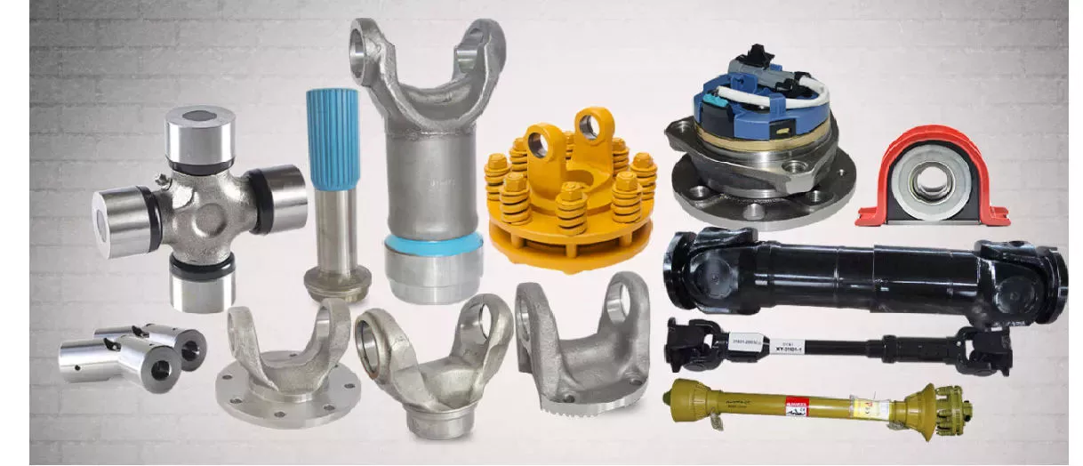
Quali fattori bisogna considerare nella scelta dell'albero di trasmissione più adatto a una specifica applicazione?
Nella scelta dell'albero di trasmissione più adatto a una specifica applicazione, è necessario considerare diversi fattori. La scelta dell'albero di trasmissione riveste un ruolo cruciale nel garantire una trasmissione di potenza efficiente e affidabile. Ecco i fattori chiave da tenere in considerazione:
1. Requisiti di potenza e coppia:
I requisiti di potenza e coppia dell'applicazione sono considerazioni essenziali. È fondamentale determinare la coppia massima che l'albero di trasmissione dovrà trasmettere senza guasti o flessioni eccessive. Ciò include la valutazione della potenza erogata dal motore o dalla fonte di energia, nonché delle richieste di coppia dei componenti azionati. La scelta di un albero di trasmissione con diametro, resistenza del materiale e design appropriati è essenziale per garantire che possa gestire i livelli di coppia previsti senza compromettere le prestazioni o la sicurezza.
2. Velocità operativa:
Un altro fattore critico è la velocità di rotazione dell'albero motore. La velocità di rotazione influenza il comportamento dinamico dell'albero motore, comprese le potenziali vibrazioni, risonanze e limitazioni di velocità critica. È importante scegliere un albero motore in grado di operare entro l'intervallo di velocità desiderato senza incorrere in vibrazioni eccessive o compromettere l'integrità strutturale. Fattori come le proprietà del materiale, l'equilibrio e l'analisi della velocità critica devono essere presi in considerazione per garantire che l'albero motore possa gestire efficacemente la velocità di rotazione richiesta.
3. Lunghezza e allineamento:
Nella scelta di un albero di trasmissione, è necessario considerare i requisiti di lunghezza e allineamento dell'applicazione. La distanza tra il motore o la fonte di energia e i componenti azionati determina la lunghezza necessaria dell'albero di trasmissione. In situazioni in cui si verificano variazioni significative di lunghezza o angoli di lavoro, potrebbero essere necessari alberi di trasmissione telescopici o alberi di trasmissione multipli con giunti o giunti cardanici appropriati. Un corretto allineamento dell'albero di trasmissione è fondamentale per ridurre al minimo le vibrazioni, limitare l'usura e garantire un'efficiente trasmissione della potenza.
4. Limitazioni di spazio:
Lo spazio disponibile all'interno dell'applicazione è un fattore importante da considerare. L'albero di trasmissione deve adattarsi allo spazio assegnato senza interferire con altri componenti o strutture. È essenziale considerare le dimensioni complessive dell'albero di trasmissione, inclusi lunghezza, diametro ed eventuali componenti aggiuntivi come giunti o accoppiamenti. In alcuni casi, potrebbe essere necessario progettare alberi di trasmissione personalizzati o compatti per far fronte alle limitazioni di spazio, pur mantenendo adeguate capacità di trasmissione della potenza.
5. Condizioni ambientali:
È necessario valutare le condizioni ambientali in cui opererà l'albero di trasmissione. Fattori come temperatura, umidità, agenti corrosivi ed esposizione a contaminanti possono influire sulle prestazioni e sulla durata dell'albero di trasmissione. È importante selezionare materiali e rivestimenti in grado di resistere alle specifiche condizioni ambientali per prevenire corrosione, degrado o guasti prematuri dell'albero di trasmissione. Considerazioni particolari possono essere necessarie per applicazioni esposte a temperature estreme, acqua, sostanze chimiche o abrasive.
6. Tipologia di applicazione e settore industriale:
Il tipo di applicazione specifico e i requisiti del settore industriale giocano un ruolo fondamentale nella scelta dell'albero di trasmissione. Diversi settori, come quello automobilistico, aerospaziale, dei macchinari industriali, agricolo o navale, presentano esigenze specifiche che devono essere soddisfatte. Comprendere le necessità specifiche e le condizioni operative dell'applicazione è cruciale per determinare il design, i materiali e le caratteristiche prestazionali più appropriati per l'albero di trasmissione. Anche il rispetto degli standard e delle normative di settore può essere un fattore da considerare in determinate applicazioni.
7. Manutenzione e funzionalità:
È importante considerare la facilità di manutenzione e di assistenza. Alcuni tipi di alberi di trasmissione possono richiedere ispezioni periodiche, lubrificazione o sostituzione di componenti. Valutare l'accessibilità dell'albero di trasmissione e i relativi requisiti di manutenzione può contribuire a ridurre al minimo i tempi di fermo e a garantire l'affidabilità a lungo termine. Anche la facilità di smontaggio e rimontaggio dell'albero di trasmissione può essere vantaggiosa per le riparazioni o la sostituzione dei componenti.
Valutando attentamente questi fattori, è possibile selezionare l'albero di trasmissione più adatto a una specifica applicazione, in grado di soddisfare le esigenze di trasmissione di potenza, le condizioni operative e i requisiti di durata, garantendo in definitiva prestazioni e affidabilità ottimali.
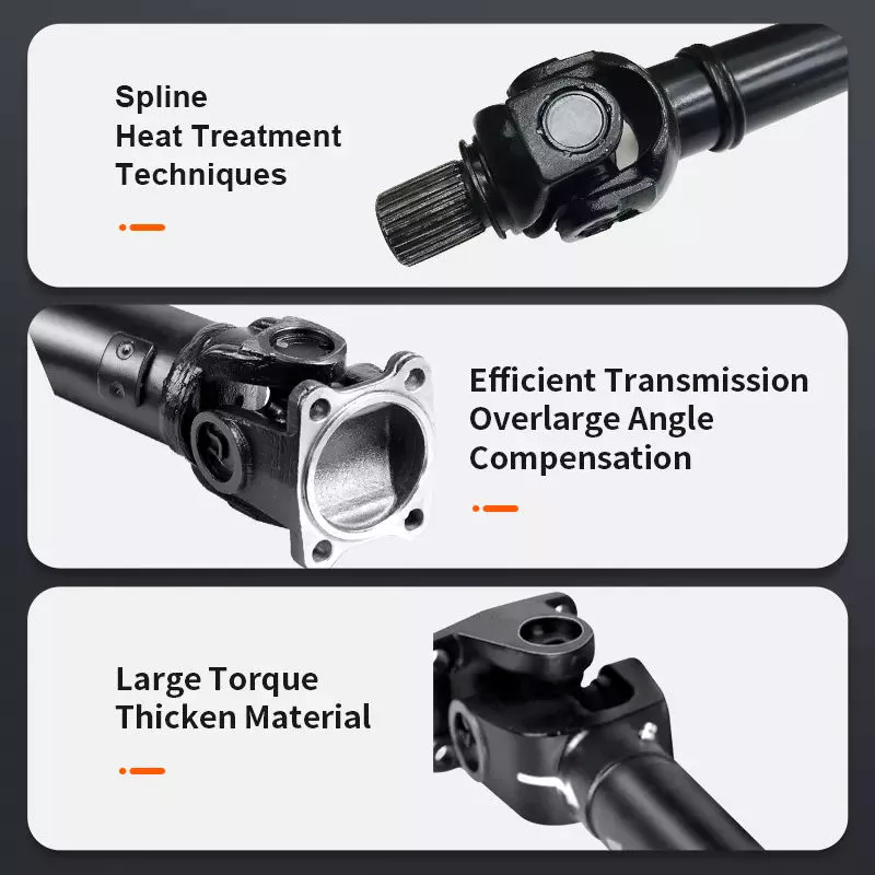
How do drive shafts contribute to the efficiency of vehicle propulsion and power transmission?
Drive shafts play a crucial role in the efficiency of vehicle propulsion and power transmission systems. They are responsible for transferring power from the engine or power source to the wheels or driven components. Here’s a detailed explanation of how drive shafts contribute to the efficiency of vehicle propulsion and power transmission:
1. Power Transfer:
Drive shafts transmit power from the engine or power source to the wheels or driven components. By efficiently transferring rotational energy, drive shafts enable the vehicle to move forward or drive the machinery. The design and construction of drive shafts ensure minimal power loss during the transfer process, maximizing the efficiency of power transmission.
2. Torque Conversion:
Drive shafts can convert torque from the engine or power source to the wheels or driven components. Torque conversion is necessary to match the power characteristics of the engine with the requirements of the vehicle or machinery. Drive shafts with appropriate torque conversion capabilities ensure that the power delivered to the wheels is optimized for efficient propulsion and performance.
3. Constant Velocity (CV) Joints:
Many drive shafts incorporate Constant Velocity (CV) joints, which help maintain a constant speed and efficient power transmission, even when the driving and driven components are at different angles. CV joints allow for smooth power transfer and minimize vibration or power losses that may occur due to changing operating angles. By maintaining constant velocity, drive shafts contribute to efficient power transmission and improved overall vehicle performance.
4. Lightweight Construction:
Efficient drive shafts are often designed with lightweight materials, such as aluminum or composite materials. Lightweight construction reduces the rotational mass of the drive shaft, which results in lower inertia and improved efficiency. Reduced rotational mass enables the engine to accelerate and decelerate more quickly, allowing for better fuel efficiency and overall vehicle performance.
5. Minimized Friction:
Efficient drive shafts are engineered to minimize frictional losses during power transmission. They incorporate features such as high-quality bearings, low-friction seals, and proper lubrication to reduce energy losses caused by friction. By minimizing friction, drive shafts enhance power transmission efficiency and maximize the available power for propulsion or operating other machinery.
6. Balanced and Vibration-Free Operation:
Drive shafts undergo dynamic balancing during the manufacturing process to ensure smooth and vibration-free operation. Imbalances in the drive shaft can lead to power losses, increased wear, and vibrations that reduce overall efficiency. By balancing the drive shaft, it can spin evenly, minimizing vibrations and optimizing power transmission efficiency.
7. Maintenance and Regular Inspection:
Proper maintenance and regular inspection of drive shafts are essential for maintaining their efficiency. Regular lubrication, inspection of joints and components, and prompt repair or replacement of worn or damaged parts help ensure optimal power transmission efficiency. Well-maintained drive shafts operate with minimal friction, reduced power losses, and improved overall efficiency.
8. Integration with Efficient Transmission Systems:
Drive shafts work in conjunction with efficient transmission systems, such as manual, automatic, or continuously variable transmissions. These transmissions help optimize power delivery and gear ratios based on driving conditions and vehicle speed. By integrating with efficient transmission systems, drive shafts contribute to the overall efficiency of the vehicle propulsion and power transmission system.
9. Aerodynamic Considerations:
In some cases, drive shafts are designed with aerodynamic considerations in mind. Streamlined drive shafts, often used in high-performance or electric vehicles, minimize drag and air resistance to improve overall vehicle efficiency. By reducing aerodynamic drag, drive shafts contribute to the efficient propulsion and power transmission of the vehicle.
10. Optimized Length and Design:
Drive shafts are designed to have optimal lengths and designs to minimize energy losses. Excessive drive shaft length or improper design can introduce additional rotational mass, increase bending stresses, and result in energy losses. By optimizing the length and design, drive shafts maximize power transmission efficiency and contribute to improved overall vehicle efficiency.
Overall, drive shafts contribute to the efficiency of vehicle propulsion and power transmission through effective power transfer, torque conversion, utilization of CV joints, lightweight construction, minimized friction, balanced operation, regular maintenance, integration with efficient transmission systems, aerodynamic considerations, and optimized length and design. By ensuring efficient power delivery and minimizing energy losses, drive shafts play a significant role in enhancing the overall efficiency and performance of vehicles and machinery.
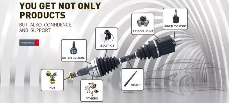
How do drive shafts handle variations in length and torque requirements?
Drive shafts are designed to handle variations in length and torque requirements in order to efficiently transmit rotational power. Here’s an explanation of how drive shafts address these variations:
Length Variations:
Drive shafts are available in different lengths to accommodate varying distances between the engine or power source and the driven components. They can be custom-made or purchased in standardized lengths, depending on the specific application. In situations where the distance between the engine and the driven components is longer, multiple drive shafts with appropriate couplings or universal joints can be used to bridge the gap. These additional drive shafts effectively extend the overall length of the power transmission system.
Additionally, some drive shafts are designed with telescopic sections. These sections can be extended or retracted, allowing for adjustments in length to accommodate different vehicle configurations or dynamic movements. Telescopic drive shafts are commonly used in applications where the distance between the engine and the driven components may change, such as in certain types of trucks, buses, and off-road vehicles.
Torque Requirements:
Drive shafts are engineered to handle varying torque requirements based on the power output of the engine or power source and the demands of the driven components. The torque transmitted through the drive shaft depends on factors such as the engine power, load conditions, and the resistance encountered by the driven components.
Manufacturers consider torque requirements when selecting the appropriate materials and dimensions for drive shafts. Drive shafts are typically made from high-strength materials, such as steel or aluminum alloys, to withstand the torque loads without deformation or failure. The diameter, wall thickness, and design of the drive shaft are carefully calculated to ensure it can handle the expected torque without excessive deflection or vibration.
In applications with high torque demands, such as heavy-duty trucks, industrial machinery, or performance vehicles, drive shafts may have additional reinforcements. These reinforcements can include thicker walls, cross-sectional shapes optimized for strength, or composite materials with superior torque-handling capabilities.
Furthermore, drive shafts often incorporate flexible joints, such as universal joints or constant velocity (CV) joints. These joints allow for angular misalignment and compensate for variations in the operating angles between the engine, transmission, and driven components. They also help absorb vibrations and shocks, reducing stress on the drive shaft and enhancing its torque-handling capacity.
In summary, drive shafts handle variations in length and torque requirements through customizable lengths, telescopic sections, appropriate materials and dimensions, and the inclusion of flexible joints. By carefully considering these factors, drive shafts can efficiently and reliably transmit power while accommodating the specific needs of different applications.


editor by CX 2024-04-03

























