
Описание продукта
1.P roduct Description
Thi s Gear shaft, Herringbone Gear Shaft, Bevel Gear, Eccentric Shaft mainly used on vessel engine, fan internal gear
2.1. Gear Shaft Processing
Gear Shaft drawing CHECK, Make Forging Mold, Forging Mold Quality Inspection Check, Machine Processing, Check Size\Hardness\Surface Finish and other technical parameters on drawing.
2.2. Herringbone Gear Shaft Package
Spray anti-rust oil on Herringbone Gear Shaft, Wrap waterproof cloth around Gear Shaft for reducer, Prepare package by shaft shape&weight to choose steel frame, steel support or wooden box etc.
2.3. OEM Customized Gear Shaft
We supply OEM SERVICE, customized herringbone gear shaft with big module, more than 1tons big weight, more than 3m length, 42CrMo/35CrMo or your specified required material gear shaft.
2.Product Technical info.
| Module | m | Range: 5~70 |
| Gear Teeth Number | z | OEM by drawing’s technical parameters |
| Teeth Height | H | OEM by drawing’s technical parameters |
| Teeth Thickness | S | OEM by drawing’s technical parameters |
| Tooth pitch | P | OEM by drawing’s technical parameters |
| Tooth addendum | Ha | OEM by drawing’s technical parameters |
| Tooth dedendum | Hf | OEM by drawing’s technical parameters |
| Working height | h’ | OEM by drawing’s technical parameters |
| Bottom clearance | C | OEM by drawing’s technical parameters |
| Pressure Angle | α | OEM by drawing’s technical parameters |
| Helix Angle, | OEM by drawing’s technical parameters | |
| Surface hardness | HRC | Range: HRC 50~HRC63(Quenching) |
| Hardness: | HB | Range: HB150~HB280; Hardening Tempering/ Hardened Tooth Surface |
| Surface finish | Range: Ra1.6~Ra3.2 | |
| Tooth surface roughness | Ra | Range: ≥0.4 |
| Gear Accuracy Grade | Grade Range: 5-6-7-8-9 (ISO 1328) | |
| Length | L | Range: 0.8m~10m |
| Weight | Kg | Range: Min. 100kg~Max. 80tons Single Piece |
| Gear Position | Internal/External Gear | |
| Toothed Portion Shape | Spur Gear/Bevel/Spiral/Helical/Straight | |
| Shaft shape | Herringbone Gear Shaft / Gear Shaft / Eccentric Shaft / Spur Gear / Girth Gear / Gear Wheel | |
| Материал | Forging/ Casting |
Forging/ Casting 45/42CrMo/40Cr or OEM |
| Manufacturing Method | Cut Gear | |
| Gear Teeth Milling | √ | |
| Gear Teeth Grinding | √ | |
| Heat Treatment | Quenching /Carburizing | |
| Sand Blasting | Null | |
| Тестирование | UT\MT | |
| Trademark | TOTEM/OEM | |
| Application | Gearbox, Reducer, Petroleum,Cement,Mining,Metallurgy etc. Wind driven generator,vertical mill reducer,oil rig helical gear,petroleum slurry pump gear shaft |
|
| Transport Package | Export package (wooden box, steel frame etc.) | |
| Origin | Китай | |
| HS Code | 8483409000 |
Material Comparison List
| STEEL CODE GRADES COMPARISON | |||||
| CHINA/GB | ISO | ГΟСТ | ASTM | JIS | DIN |
| 45 | C45E4 | 45 | 1045 | S45C | CK45 |
| 40Cr | 41Cr4 | 40X | 5140 | SCr440 | 41Cr4 |
| 20CrMo | 18CrMo4 | 20ХМ | 4118 | SCM22 | 25CrMo4 |
| 42CrMo | 42CrMo4 | 38XM | 4140 | SCM440 | 42CrMo4 |
| 20CrMnTi | 18XГT | SMK22 | |||
| 20Cr2Ni4 | 20X2H4A | ||||
| 20CrNiMo | 20CrNiMo2 | 20XHM | 8720 | SNCM220 | 21NiCrMo2 |
| 40CrNiMoA | 40XH2MA/ 40XHMA |
4340 | SNCM439 | 40NiCrMo6/ 36NiCrMo4 |
|
| 20CrNi2Mo | 20NiCrMo7 | 20XH2MA | 4320 | SNCM420 | |
3.Totem Service
TOTEM Machinery focus on supplying GEAR SHAFT, ECCENTRIC SHAFT, HERRINGBONE GEAR, BEVEL GEAR, INTERNAL GEAR and other parts for transmission devices & equipments(large industrial reducers & drivers). Which were mainly used in the fields of port facilities, cement, mining, metallurgical industry etc. We invested in several machine processing factories,forging factories and casting factories,relies on these strong reliable and high-quality supplier network, to let our customers worry free.
TOTEM Philosophy: Quality-No.1, Integrity- No.1, Service- No.1
24hrs Salesman on-line, guarantee quick and positive feedback. Experienced and Professional Forwarder Guarantee Log. transportation.
4.About TOTEM
1. Workshop & Processing Strength
2. Testing Facilities
3. Customer Inspection & Shipping
5. Contact Us
ZheJiang CZPT Machinery Co.,Ltd
Facebook: ZheJiang Totem
/* 22 января 2571 19:08:37 */!function(){function s(e,r){var a,o={};try{e&&e.split(“,).forEach(function(e,t){e&&(a=e.match(/(.*?):(.*)$/))&&1
| Материал: | Легированная сталь |
|---|---|
| Нагрузка: | карданный вал |
| Жесткость и гибкость: | Ковка |
| Точность размеров диаметра цапфы: | It5-It9 |
| Форма оси: | Прямой вал |
| Форма вала: | Индивидуальный |
| Настройка: |
Доступный
| Индивидуальный запрос |
|---|
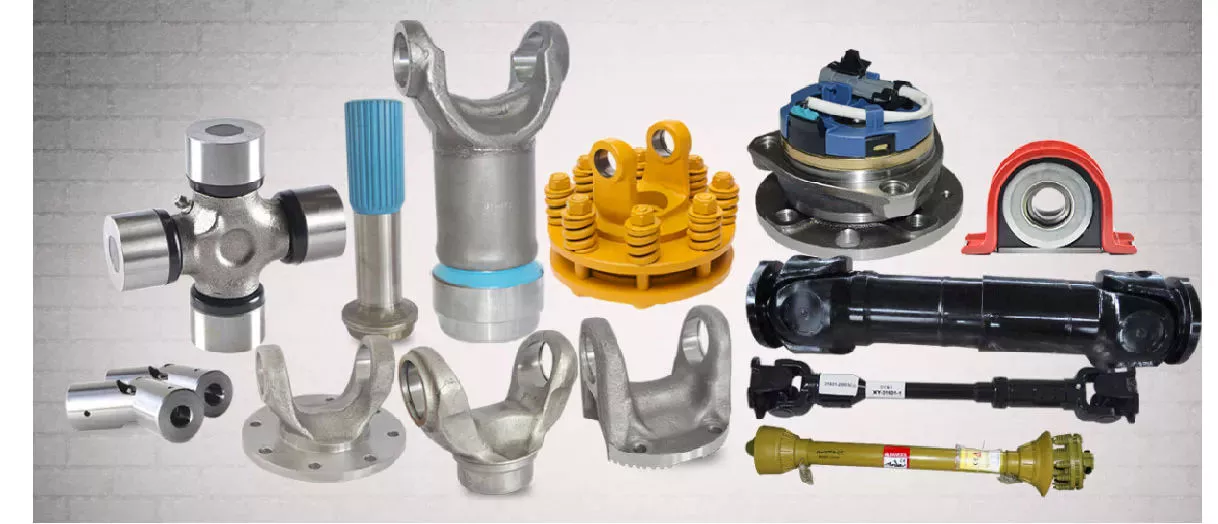
Какие факторы следует учитывать при выборе подходящего карданного вала для конкретного применения?
При выборе подходящего карданного вала для конкретного применения необходимо учитывать несколько факторов. Выбор карданного вала играет решающую роль в обеспечении эффективной и надежной передачи мощности. Вот основные факторы, которые следует учитывать:
1. Требования к мощности и крутящему моменту:
Требования к мощности и крутящему моменту, предъявляемые к данному применению, являются важнейшими факторами. Крайне важно определить максимальный крутящий момент, который должен передавать приводной вал без поломок или чрезмерного прогиба. Это включает в себя оценку выходной мощности двигателя или источника питания, а также требований к крутящему моменту приводимых компонентов. Выбор приводного вала с соответствующим диаметром, прочностью материала и конструкцией имеет важное значение для обеспечения его способности выдерживать ожидаемые уровни крутящего момента без ущерба для производительности или безопасности.
2. Рабочая скорость:
Рабочая скорость приводного вала — ещё один критически важный фактор. Скорость вращения влияет на динамическое поведение приводного вала, включая потенциальную вибрацию, резонанс и ограничения критической скорости. Важно выбрать приводной вал, который сможет работать в желаемом диапазоне скоростей без чрезмерных вибраций или нарушения структурной целостности. Для обеспечения эффективной работы приводного вала на требуемой скорости следует учитывать такие факторы, как свойства материала, балансировка и анализ критической скорости.
3. Длина и выравнивание:
При выборе карданного вала необходимо учитывать требования к длине и соосности, предъявляемые к конкретному применению. Расстояние между двигателем или источником энергии и приводимыми в движение компонентами определяет необходимую длину карданного вала. В ситуациях, когда наблюдаются значительные колебания длины или углов наклона, могут потребоваться телескопические карданные валы или несколько карданных валов с соответствующими муфтами или карданными шарнирами. Правильная соосность карданного вала имеет решающее значение для минимизации вибраций, снижения износа и обеспечения эффективной передачи мощности.
4. Ограничения по площади:
Важным фактором является доступное пространство внутри устройства. Приводной вал должен помещаться в отведенное пространство, не мешая другим компонентам или конструкциям. Необходимо учитывать габаритные размеры приводного вала, включая длину, диаметр и любые дополнительные компоненты, такие как шарниры или муфты. В некоторых случаях для компенсации ограниченного пространства при сохранении достаточной мощности передачи могут потребоваться нестандартные или компактные конструкции приводных валов.
5. Условия окружающей среды:
Необходимо оценить условия окружающей среды, в которых будет работать приводной вал. Такие факторы, как температура, влажность, коррозионные вещества и воздействие загрязнений, могут повлиять на производительность и срок службы приводного вала. Важно выбрать материалы и покрытия, способные выдерживать конкретные условия окружающей среды, чтобы предотвратить коррозию, деградацию или преждевременный выход приводного вала из строя. Особые меры могут потребоваться для применений, подверженных воздействию экстремальных температур, воды, химических веществ или абразивных материалов.
6. Тип применения и отрасль:
При выборе карданного вала важную роль играют конкретный тип применения и отраслевые требования. Различные отрасли, такие как автомобильная, аэрокосмическая, машиностроительная, сельскохозяйственная или морская, имеют уникальные требования, которые необходимо учитывать. Понимание специфических потребностей и условий эксплуатации имеет решающее значение для определения соответствующей конструкции карданного вала, материалов и характеристик его работы. В некоторых областях применения также может учитываться соответствие отраслевым стандартам и нормам.
7. Техническое обслуживание и ремонтопригодность:
При выборе приводного вала следует учитывать простоту обслуживания и ремонтопригодность. Некоторые конструкции могут требовать периодического осмотра, смазки или замены компонентов. Учет доступности приводного вала и связанных с этим требований к техническому обслуживанию может помочь минимизировать время простоя и обеспечить долгосрочную надежность. Простота разборки и сборки приводного вала также может быть полезна для ремонта или замены компонентов.
Тщательно учитывая эти факторы, можно выбрать подходящий карданный вал для конкретного применения, который будет соответствовать потребностям в передаче мощности, условиям эксплуатации и требованиям к долговечности, что в конечном итоге обеспечит оптимальную производительность и надежность.
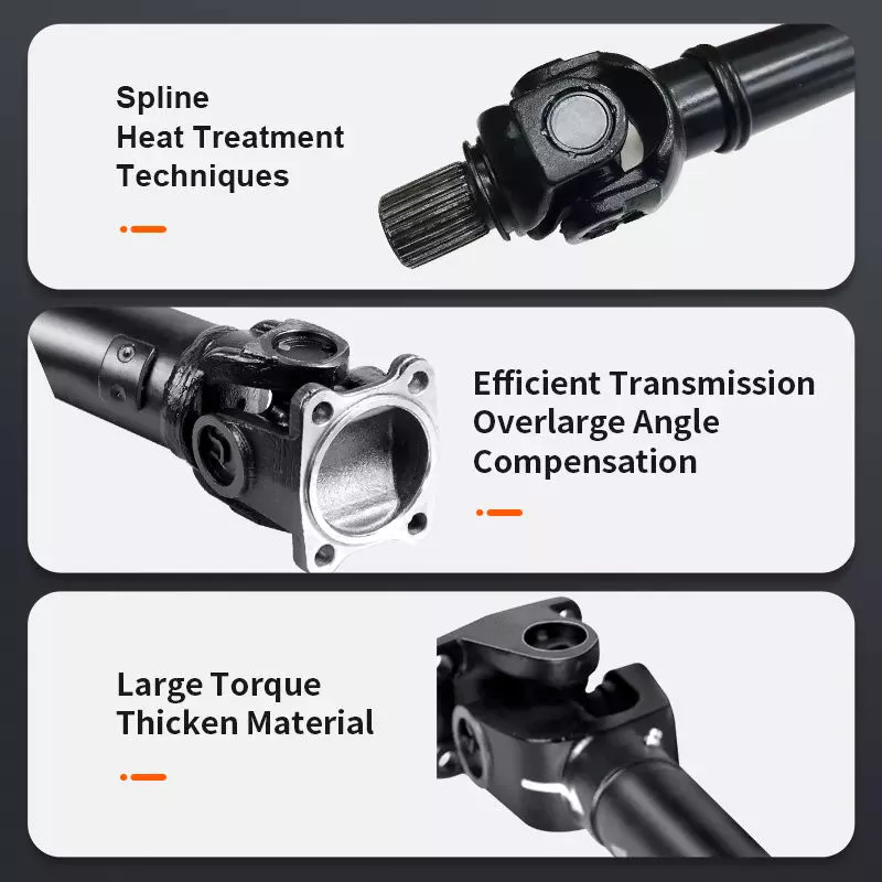
How do drive shafts contribute to the efficiency of vehicle propulsion and power transmission?
Drive shafts play a crucial role in the efficiency of vehicle propulsion and power transmission systems. They are responsible for transferring power from the engine or power source to the wheels or driven components. Here’s a detailed explanation of how drive shafts contribute to the efficiency of vehicle propulsion and power transmission:
1. Power Transfer:
Drive shafts transmit power from the engine or power source to the wheels or driven components. By efficiently transferring rotational energy, drive shafts enable the vehicle to move forward or drive the machinery. The design and construction of drive shafts ensure minimal power loss during the transfer process, maximizing the efficiency of power transmission.
2. Torque Conversion:
Drive shafts can convert torque from the engine or power source to the wheels or driven components. Torque conversion is necessary to match the power characteristics of the engine with the requirements of the vehicle or machinery. Drive shafts with appropriate torque conversion capabilities ensure that the power delivered to the wheels is optimized for efficient propulsion and performance.
3. Constant Velocity (CV) Joints:
Many drive shafts incorporate Constant Velocity (CV) joints, which help maintain a constant speed and efficient power transmission, even when the driving and driven components are at different angles. CV joints allow for smooth power transfer and minimize vibration or power losses that may occur due to changing operating angles. By maintaining constant velocity, drive shafts contribute to efficient power transmission and improved overall vehicle performance.
4. Lightweight Construction:
Efficient drive shafts are often designed with lightweight materials, such as aluminum or composite materials. Lightweight construction reduces the rotational mass of the drive shaft, which results in lower inertia and improved efficiency. Reduced rotational mass enables the engine to accelerate and decelerate more quickly, allowing for better fuel efficiency and overall vehicle performance.
5. Minimized Friction:
Efficient drive shafts are engineered to minimize frictional losses during power transmission. They incorporate features such as high-quality bearings, low-friction seals, and proper lubrication to reduce energy losses caused by friction. By minimizing friction, drive shafts enhance power transmission efficiency and maximize the available power for propulsion or operating other machinery.
6. Balanced and Vibration-Free Operation:
Drive shafts undergo dynamic balancing during the manufacturing process to ensure smooth and vibration-free operation. Imbalances in the drive shaft can lead to power losses, increased wear, and vibrations that reduce overall efficiency. By balancing the drive shaft, it can spin evenly, minimizing vibrations and optimizing power transmission efficiency.
7. Maintenance and Regular Inspection:
Proper maintenance and regular inspection of drive shafts are essential for maintaining their efficiency. Regular lubrication, inspection of joints and components, and prompt repair or replacement of worn or damaged parts help ensure optimal power transmission efficiency. Well-maintained drive shafts operate with minimal friction, reduced power losses, and improved overall efficiency.
8. Integration with Efficient Transmission Systems:
Drive shafts work in conjunction with efficient transmission systems, such as manual, automatic, or continuously variable transmissions. These transmissions help optimize power delivery and gear ratios based on driving conditions and vehicle speed. By integrating with efficient transmission systems, drive shafts contribute to the overall efficiency of the vehicle propulsion and power transmission system.
9. Aerodynamic Considerations:
In some cases, drive shafts are designed with aerodynamic considerations in mind. Streamlined drive shafts, often used in high-performance or electric vehicles, minimize drag and air resistance to improve overall vehicle efficiency. By reducing aerodynamic drag, drive shafts contribute to the efficient propulsion and power transmission of the vehicle.
10. Optimized Length and Design:
Drive shafts are designed to have optimal lengths and designs to minimize energy losses. Excessive drive shaft length or improper design can introduce additional rotational mass, increase bending stresses, and result in energy losses. By optimizing the length and design, drive shafts maximize power transmission efficiency and contribute to improved overall vehicle efficiency.
Overall, drive shafts contribute to the efficiency of vehicle propulsion and power transmission through effective power transfer, torque conversion, utilization of CV joints, lightweight construction, minimized friction, balanced operation, regular maintenance, integration with efficient transmission systems, aerodynamic considerations, and optimized length and design. By ensuring efficient power delivery and minimizing energy losses, drive shafts play a significant role in enhancing the overall efficiency and performance of vehicles and machinery.
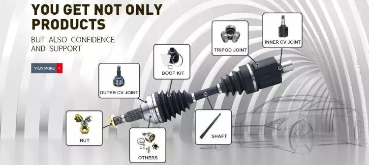
How do drive shafts handle variations in length and torque requirements?
Drive shafts are designed to handle variations in length and torque requirements in order to efficiently transmit rotational power. Here’s an explanation of how drive shafts address these variations:
Length Variations:
Drive shafts are available in different lengths to accommodate varying distances between the engine or power source and the driven components. They can be custom-made or purchased in standardized lengths, depending on the specific application. In situations where the distance between the engine and the driven components is longer, multiple drive shafts with appropriate couplings or universal joints can be used to bridge the gap. These additional drive shafts effectively extend the overall length of the power transmission system.
Additionally, some drive shafts are designed with telescopic sections. These sections can be extended or retracted, allowing for adjustments in length to accommodate different vehicle configurations or dynamic movements. Telescopic drive shafts are commonly used in applications where the distance between the engine and the driven components may change, such as in certain types of trucks, buses, and off-road vehicles.
Torque Requirements:
Drive shafts are engineered to handle varying torque requirements based on the power output of the engine or power source and the demands of the driven components. The torque transmitted through the drive shaft depends on factors such as the engine power, load conditions, and the resistance encountered by the driven components.
Manufacturers consider torque requirements when selecting the appropriate materials and dimensions for drive shafts. Drive shafts are typically made from high-strength materials, such as steel or aluminum alloys, to withstand the torque loads without deformation or failure. The diameter, wall thickness, and design of the drive shaft are carefully calculated to ensure it can handle the expected torque without excessive deflection or vibration.
In applications with high torque demands, such as heavy-duty trucks, industrial machinery, or performance vehicles, drive shafts may have additional reinforcements. These reinforcements can include thicker walls, cross-sectional shapes optimized for strength, or composite materials with superior torque-handling capabilities.
Furthermore, drive shafts often incorporate flexible joints, such as universal joints or constant velocity (CV) joints. These joints allow for angular misalignment and compensate for variations in the operating angles between the engine, transmission, and driven components. They also help absorb vibrations and shocks, reducing stress on the drive shaft and enhancing its torque-handling capacity.
In summary, drive shafts handle variations in length and torque requirements through customizable lengths, telescopic sections, appropriate materials and dimensions, and the inclusion of flexible joints. By carefully considering these factors, drive shafts can efficiently and reliably transmit power while accommodating the specific needs of different applications.


editor by CX 2024-04-03

























