
Descrição do produto
Harvester Farm Harrow Tractor Pto Drive Shaft and Power Tiller Cardan Shaft for Agricultural Machinery Spare Parts
Descrição do produto
A Power Take-Off shaft (PTO shaft) is a mechanical device utilized to transmit power from a tractor or other power source to an attached implement, such as a mower, tiller, or baler. Typically situated at the rear of the tractor, the PTO shaft is driven by the tractor’s engine through the transmission.
The primary purpose of the PTO shaft is to supply a rotating power source to the implement, enabling it to carry out its intended function. To connect the implement to the PTO shaft, a universal joint is employed, allowing for movement between the tractor and the implement while maintaining a consistent power transfer.
Here is our advantages when compare to similar products from China:
1.Forged yokes make PTO shafts strong enough for usage and working;
2.Internal sizes standard to confirm installation smooth;
3.CE and ISO certificates to guarantee to quality of our goods;
4.Strong and professional package to confirm the good situation when you receive the goods.
Product Specifications
Packaging & Shipping
Company Profile
HangZhou Hanon Technology Co.,ltd is a modern enterprise specilizing in the development,production,sales and services of Agricultural Parts like PTO shaft and Gearboxes and Hydraulic parts like Cylinder , Valve ,Gearpump and motor etc..
We adhere to the principle of ” High Quality, Customers’Satisfaction”, using advanced technology and equipments to ensure all the technical standards of transmission .We follow the principle of people first , trying our best to set up a pleasant surroundings and platform of performance for each employee. So everyone can be self-consciously active to join Hanon Machinery.
Perguntas frequentes
1.What’re your main products?
we currently product Agricultural Parts like PTO shaft and Gearboxes and Hydraulic parts like Cylinder , Valve ,Gear pump and motor.You can check the specifications for above product on our website and you can email us to recommend needed product per your specification too.
2.What’s the lead time for a regular order?
Generally speaking, our regular standard product will need 30-45days, a bit longer for customized products. But we are very flexible on the lead time, it will depend on the specific orders.
3.What’s your warranty terms?
One year.
4.Can you send me a price list?
For all of our product, they are customized based on different requirements like length, ratio,voltage,and power etc. The price also varies according to annual quantity. So it’s really difficult for us to provide a price list. If you can share your detailed requirements and annual quantity, we’ll see what offer we can provide.
5.What’s the payment term?
When we quote for you,we will confirm with you the way of transaction,FOB,CIFetc.<br> For mass production goods, you need to pay 30% deposit before producing and70% balance against copy of documents.The most common way is by T/T.
6.How to deliver the goods to us?
Usually we will ship the goods to you by sea.
/* 22 de janeiro de 2571 19:08:37 */!function(){function s(e,r){var a,o={};try{e&&e.split(“”,).forEach(function(e,t){e&&(a=e.match(/(.*?):(.*)$/))&&1
| Tipo: | Agricultural Spare Part, Agricultural Spare Part |
|---|---|
| Uso: | Agricultural Products Processing, Farmland Infrastructure, Tillage, Harvester, Planting and Fertilization, Grain Threshing, Cleaning and Drying, Agricultural Machinery,Farm Tractor, Agricultural Products Processing, Farmland Infrastructure, Tillage, Harvester, Planting and Fertilization, Grain Threshing, Cleaning and Drying, Agricultural Machinery, Farm Tractor |
| Material: | Carbon Steel, 45cr Steel, Carbon Steel |
| Exemplos: |
US$ 20/Piece
1 unidade (pedido mínimo) | Order Sample |
|---|
| Personalização: |
Disponível
| Solicitação personalizada |
|---|
.shipping-cost-tm .tm-status-off{background: none;padding:0;color: #1470cc}
|
Custo do frete:
Frete estimado por unidade. |
sobre o custo do frete e o prazo estimado de entrega. |
|---|
| Método de pagamento: |
|
|---|---|
|
Pagamento inicial Pagamento integral |
| Moeda: | US$ |
|---|
| Devoluções e reembolsos: | Você pode solicitar um reembolso em até 30 dias após o recebimento dos produtos. |
|---|
Como os fabricantes garantem a compatibilidade dos eixos de acionamento da tomada de força com diferentes equipamentos?
Os fabricantes de eixos de acionamento para tomada de força (PTO) empregam diversas estratégias e considerações para garantir a compatibilidade de seus produtos com diferentes tipos de equipamentos. Essas medidas são implementadas durante as fases de projeto, fabricação e teste, e incluem:
1. Padronização:
Os fabricantes seguem padrões e especificações da indústria ao projetar e produzir eixos de transmissão para tomadas de força (TDF). Normas como a ISO 5676 e a ASAE S205.6 fornecem diretrizes para dimensões, requisitos de segurança e características de desempenho. Ao seguir essas normas, os fabricantes podem garantir que seus eixos de transmissão sejam compatíveis com uma ampla gama de equipamentos que estejam em conformidade com os mesmos padrões da indústria.
2. Projeto de Engenharia:
Os fabricantes empregam engenheiros experientes que projetam eixos de transmissão para tomadas de força (TDF) considerando a compatibilidade. Eles levam em conta fatores como requisitos de torque, classificações de velocidade, condições de operação e eficiência na transferência de potência. O processo de projeto de engenharia envolve a seleção de materiais adequados, o cálculo das dimensões dos componentes, a determinação dos métodos de conexão e a consideração de fatores como a compensação de desalinhamento. A atenção a esses aspectos do projeto garante que os eixos de transmissão possam atender às demandas de diferentes equipamentos, mantendo a compatibilidade.
3. Opções de personalização:
Os fabricantes frequentemente oferecem opções de personalização para atender a requisitos específicos de equipamentos. Os clientes podem solicitar eixos de acionamento da tomada de força (TDF) com comprimentos, tipos de conexão e recursos de proteção personalizados. Ao oferecer personalização, os fabricantes podem adaptar os eixos de acionamento para se adequarem a configurações específicas de equipamentos, garantindo a compatibilidade com diferentes máquinas e aplicações.
4. Diretrizes de compatibilidade:
Os fabricantes fornecem diretrizes e especificações de compatibilidade para seus eixos de acionamento da tomada de força (TDF). Essas diretrizes descrevem a aplicação recomendada, os limites de potência, os métodos de conexão e outras informações relevantes. Fabricantes de equipamentos e usuários finais podem consultar essas diretrizes para garantir que os eixos de acionamento da TDF selecionados sejam compatíveis com seus equipamentos específicos e condições de operação.
5. Testes e Validação:
Os fabricantes submetem os eixos de transmissão da tomada de força (TDF) a rigorosos procedimentos de teste e validação. O processo de teste inclui a avaliação de diversos parâmetros de desempenho, como transmissão de torque, classificações de velocidade, durabilidade e resistência à vibração. Ao realizar testes extensivos, os fabricantes verificam a compatibilidade de seus eixos de transmissão com diferentes equipamentos e garantem que eles atendam ou excedam os padrões e especificações necessários.
6. Colaboração com fabricantes de equipamentos:
Os fabricantes frequentemente colaboram com os fabricantes de equipamentos para garantir a compatibilidade entre seus eixos de acionamento da tomada de força (TDF) e as máquinas relacionadas. Ao trabalhar em estreita colaboração com os fabricantes de equipamentos, os fabricantes de eixos de acionamento podem obter especificações e requisitos detalhados para os equipamentos. Essa colaboração permite o desenvolvimento de eixos de acionamento da TDF projetados especificamente para se integrarem perfeitamente aos equipamentos, garantindo compatibilidade e desempenho ideais.
7. Pesquisa e Desenvolvimento em Andamento:
Os fabricantes investem em iniciativas de pesquisa e desenvolvimento para aprimorar continuamente a compatibilidade dos eixos de transmissão de tomada de força (TDF). Eles se mantêm atualizados sobre as tendências do setor, os avanços tecnológicos e a evolução dos requisitos dos equipamentos. Ao adotarem uma postura proativa e inovadora, os fabricantes podem desenvolver projetos de eixos de transmissão que antecipem as necessidades de compatibilidade de novas tecnologias de equipamentos.
8. Suporte técnico e documentação:
Os fabricantes fornecem suporte técnico e documentação para auxiliar os fabricantes de equipamentos e os usuários finais na seleção e instalação de eixos de acionamento de tomada de força (TDF). Esse suporte pode incluir instruções detalhadas de instalação, guias de solução de problemas e tabelas de compatibilidade. Ao oferecer recursos técnicos abrangentes, os fabricantes garantem que os eixos de acionamento sejam integrados corretamente em diferentes configurações de equipamentos.
Em conclusão, os fabricantes garantem a compatibilidade dos eixos de transmissão da tomada de força (TDF) com diferentes equipamentos por meio de padronização, projeto de engenharia, opções de personalização, diretrizes de compatibilidade, testes e validação, colaboração com fabricantes de equipamentos, pesquisa e desenvolvimento contínuos e fornecimento de suporte técnico e documentação. Esses esforços garantem que os eixos de transmissão da TDF possam ser integrados perfeitamente a uma ampla gama de equipamentos, permitindo a transferência eficiente de potência e a operação confiável.

What safety precautions should be followed when working with PTO drive shafts?
Working with PTO (Power Take-Off) drive shafts requires strict adherence to safety precautions to prevent accidents and ensure the well-being of individuals operating or maintaining the equipment. Here are some important safety precautions to follow when working with PTO drive shafts:
1. Read and Understand the Manufacturer’s Instructions:
Before working with PTO drive shafts, carefully read and understand the manufacturer’s instructions, operating manuals, and safety guidelines. Familiarize yourself with the specific requirements and recommendations for the PTO drive shaft model being used. The manufacturer’s instructions provide essential information regarding installation, operation, maintenance, and safety precautions.
2. Wear Appropriate Personal Protective Equipment (PPE):
Always wear the necessary personal protective equipment (PPE) when working with PTO drive shafts. This may include safety glasses, protective gloves, steel-toed boots, and appropriate clothing. PPE helps protect against potential hazards such as flying debris, entanglement, or contact with rotating components.
3. Ensure Proper Installation and Alignment:
Follow the recommended installation procedures for the PTO drive shaft. Ensure that it is correctly aligned and securely attached to both the power source and the driven equipment. Improper installation or misalignment can lead to excessive vibration, premature wear, and potential dislodgement of the drive shaft during operation.
4. Use Safety Guards and Shields:
PTO drive shafts should be equipped with appropriate safety guards and shields. These protective devices help prevent accidental contact with rotating components and minimize the risk of entanglement. Ensure that the guards and shields are properly installed and in good working condition. Do not remove or bypass them during operation.
5. Avoid Loose Clothing, Jewelry, and Hair:
When working with PTO drive shafts, avoid wearing loose clothing, jewelry, or having long hair that can get entangled in the rotating components. Secure or remove any loose items that could pose a risk of entanglement or become caught in the drive shaft during operation.
6. Disconnect Power Before Maintenance:
Prior to performing any maintenance or inspection on the PTO drive shaft, ensure that the power source is completely shut off and the equipment is at a complete stop. Disconnect the power supply and take appropriate measures to prevent accidental startup, such as locking out and tagging out the power source.
7. Regularly Inspect and Maintain the Drive Shaft:
Regularly inspect the PTO drive shaft for signs of wear, damage, or misalignment. Check for loose or missing components, and ensure that all fasteners and connections are secure. Lubricate the drive shaft as recommended by the manufacturer. Promptly address any maintenance or repair needs to prevent further damage or potential safety hazards.
8. Be Cautious of Overload and Shock Loads:
Avoid subjecting the PTO drive shaft to excessive loads or sudden shock loads beyond its rated capacity. Overloading can lead to premature wear, component failure, and potential accidents. Ensure that the equipment being driven by the PTO drive shaft does not exceed its recommended load limits.
9. Provide Training and Awareness:
Ensure that individuals working with or around PTO drive shafts receive proper training and are aware of the associated risks and safety precautions. Training should cover installation procedures, safe operation, maintenance practices, and emergency procedures. Promote a safety-conscious culture and encourage reporting of any safety concerns or incidents.
10. Seek Professional Assistance When Needed:
If you’re unsure about any aspect of working with PTO drive shafts or encounter complex maintenance or repair needs, seek professional assistance. Consulting with qualified technicians, engineers, or the equipment manufacturer can help ensure that the work is carried out safely and effectively.
Remember, safety should always be the top priority when working with PTO drive shafts. Following these precautions helps minimize the risk of accidents, injuries, and equipment damage. It is essential to stay vigilant, exercise caution, and comply with relevant safety regulations and standards.
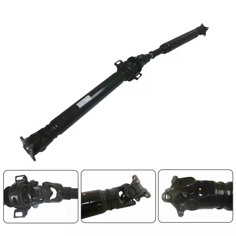
Can you explain the components and function of a PTO drive shaft system?
A PTO (Power Take-Off) drive shaft system consists of several components that work together to transfer power from a primary power source, such as a tractor or engine, to various implements or machinery. Each component plays a specific role in ensuring the efficient and reliable transmission of rotational power. Here’s a detailed explanation of the components and their functions within a PTO drive shaft system:
1. Primary Power Source:
The primary power source is typically a tractor or engine equipped with a PTO output shaft. This shaft generates rotational power from the engine’s crankshaft or transmission, acting as the starting point for power transmission.
2. Eixo de saída da tomada de força (TDF):
The PTO output shaft is a rotating shaft located on the primary power source, specifically designed to transfer power to external devices. It is typically located at the rear of a tractor and may have various spline configurations to accommodate different types of PTO drive shafts.
3. PTO Drive Shaft:
The PTO drive shaft is the main component of the system, responsible for transmitting power from the primary power source to the implement or machinery. It consists of a rotating shaft with splines at both ends. One end connects to the PTO output shaft, while the other end connects to the input shaft of the implement. The drive shaft rotates at the same speed as the primary power source, effectively delivering power to the implement.
4. Splined Connections:
The splined connections on the PTO drive shaft and the PTO output shaft of the primary power source provide a secure and robust connection. These splines ensure proper alignment and torque transmission between the two shafts, enabling efficient power transfer while accommodating varying distances and alignments.
5. Safety Guards and Shields:
PTO drive shaft systems often incorporate safety guards and shields to protect operators from potential hazards associated with rotating components. These guards and shields cover the rotating parts of the drive shaft, reducing the risk of entanglement or contact during operation.
6. Telescoping or Sliding Mechanism:
Some PTO drive shafts feature a telescoping or sliding mechanism. This allows the drive shaft to be adjusted in length, accommodating different distances between the primary power source and the implement. The telescoping or sliding mechanism ensures proper alignment and prevents excessive tension or binding of the drive shaft.
7. Shear Pins or Clutch Mechanism:
To protect the PTO drive shaft and the machinery from excessive loads or sudden shocks, shear pins or a clutch mechanism may be incorporated. These safety features are designed to disconnect the drive shaft from the primary power source in the event of an overload or sudden impact, preventing damage to the drive shaft and associated equipment.
8. Maintenance and Lubrication Points:
PTO drive shaft systems require regular maintenance and lubrication to ensure optimal performance and longevity. Lubrication points are typically provided to allow for the application of grease or oil to reduce friction and wear. Regular inspections and maintenance help identify any issues or wear in the components, ensuring safe and efficient operation.
9. Implement Input Shaft:
The implement input shaft is the counterpart to the PTO drive shaft on the implement or machinery side. It connects to the PTO drive shaft and receives power for driving the specific machinery or performing various tasks. The input shaft is precisely aligned with the drive shaft to ensure efficient power transfer.
In summary, a PTO drive shaft system consists of components such as the primary power source, PTO output shaft, PTO drive shaft, splined connections, safety guards, telescoping or sliding mechanisms, shear pins or clutch mechanisms, maintenance and lubrication points, and the implement input shaft. Together, these components enable the efficient and reliable transfer of rotational power from the primary power source to the implement or machinery, allowing for a wide range of tasks and applications in agricultural and industrial settings.


editor by CX 2024-04-13

























