
Opis produktu
Harvester Farm Harrow Tractor Pto Drive Shaft and Power Tiller Cardan Shaft for Agricultural Machinery Spare Parts
Opis produktu
Wał odbioru mocy (WOM) to urządzenie mechaniczne służące do przenoszenia mocy z ciągnika lub innego źródła zasilania na podłączone narzędzie, takie jak kosiarka, glebogryzarka lub prasa. Zazwyczaj znajduje się z tyłu ciągnika i jest napędzany przez silnik ciągnika za pośrednictwem przekładni.
Głównym celem wału odbioru mocy (WOM) jest dostarczanie obrotowego źródła napędu do narzędzia, umożliwiając mu wykonywanie jego funkcji. Do połączenia narzędzia z wałkiem WOM stosuje się przegub krzyżakowy, który umożliwia ruch między ciągnikiem a narzędziem, zapewniając jednocześnie stałe przenoszenie mocy.
Oto nasze zalety w porównaniu do podobnych produktów z Chin:
1. Kute jarzma sprawiają, że wałek odbioru mocy jest wystarczająco mocny do użytkowania i pracy;
2. Standardowe wymiary wewnętrzne w celu potwierdzenia płynnego montażu;
3. Certyfikaty CE i ISO są gwarancją jakości naszych towarów;
4. Mocne i profesjonalne opakowanie, które potwierdzi dobry stan towaru po jego otrzymaniu.
Specyfikacja produktu
Opakowanie i wysyłka
Profil firmy
HangZhou Hanon Technology Co.,ltd to nowoczesne przedsiębiorstwo specjalizujące się w rozwoju, produkcji, sprzedaży i serwisie części rolniczych, takich jak wały odbioru mocy i skrzynie biegów, a także części hydraulicznych, takich jak cylindry, zawory, pompy zębate i silniki itp.
Kierujemy się zasadą „Wysoka Jakość, Satysfakcja Klienta”, wykorzystując zaawansowane technologie i sprzęt, aby zapewnić wszystkie standardy techniczne transmisji. Kierujemy się zasadą „ludzie na pierwszym miejscu”, dokładając wszelkich starań, aby stworzyć przyjemne otoczenie i platformę wydajności dla każdego pracownika. Dzięki temu każdy może świadomie dołączyć do Hanon Machinery.
Często zadawane pytania
1.What’re your main products?
we currently product Agricultural Parts like PTO shaft and Gearboxes and Hydraulic parts like Cylinder , Valve ,Gear pump and motor.You can check the specifications for above product on our website and you can email us to recommend needed product per your specification too.
2.What’s the lead time for a regular order?
Generally speaking, our regular standard product will need 30-45days, a bit longer for customized products. But we are very flexible on the lead time, it will depend on the specific orders.
3.What’s your warranty terms?
One year.
4.Can you send me a price list?
For all of our product, they are customized based on different requirements like length, ratio,voltage,and power etc. The price also varies according to annual quantity. So it’s really difficult for us to provide a price list. If you can share your detailed requirements and annual quantity, we’ll see what offer we can provide.
5.What’s the payment term?
Kiedy będziemy przygotowywać dla Ciebie wycenę, potwierdzimy Ci metodę transakcji, FOB, CIF itp.<br> W przypadku towarów produkowanych masowo należy wpłacić depozyt w wysokości 30% przed produkcją, a resztę w wysokości 70% na podstawie kopii dokumentów. Najczęstszą formą płatności jest przelew bankowy.
6.How to deliver the goods to us?
Zazwyczaj wysyłamy towary drogą morską.
/* 22 stycznia 2571 19:08:37 */!function(){function s(e,r){var a,o={};try{e&&e.split(„”,).forEach(function(e,t){e&&(a=e.match(/(.*?):(.*)$/))&&1
| Typ: | Agricultural Spare Part, Agricultural Spare Part |
|---|---|
| Stosowanie: | Agricultural Products Processing, Farmland Infrastructure, Tillage, Harvester, Planting and Fertilization, Grain Threshing, Cleaning and Drying, Agricultural Machinery,Farm Tractor, Agricultural Products Processing, Farmland Infrastructure, Tillage, Harvester, Planting and Fertilization, Grain Threshing, Cleaning and Drying, Agricultural Machinery, Farm Tractor |
| Tworzywo: | Carbon Steel, 45cr Steel, Carbon Steel |
| Próbki: |
US$ 20/sztuka
1 sztuka (minimalne zamówienie) | Order Sample |
|---|
| Personalizacja: |
Dostępny
| Spersonalizowane żądanie |
|---|
.shipping-cost-tm .tm-status-off{background: none;padding:0;color: #1470cc}
|
Koszt wysyłki:
Szacowany koszt frachtu na jednostkę. |
about shipping cost and estimated delivery time. |
|---|
| Payment Method: |
|
|---|---|
|
Initial Payment Full Payment |
| Currency: | US$ |
|---|
| Return&refunds: | You can apply for a refund up to 30 days after receipt of the products. |
|---|
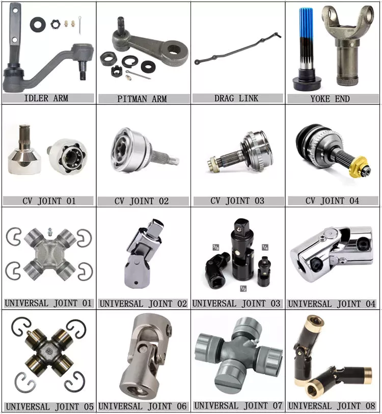
W jaki sposób producenci zapewniają kompatybilność wałów napędowych WOM z różnymi urządzeniami?
Producenci wałów napędowych WOM (WOM) stosują różne strategie i rozważania, aby zapewnić kompatybilność swoich produktów z różnymi typami sprzętu. Środki te są wdrażane na etapie projektowania, produkcji i testowania i obejmują:
1. Standaryzacja:
Producenci przestrzegają norm i specyfikacji branżowych podczas projektowania i produkcji wałów napędowych WOM. Normy takie jak ISO 5676 i ASAE S205.6 zawierają wytyczne dotyczące wymiarów, wymagań bezpieczeństwa i parametrów eksploatacyjnych. Przestrzegając tych norm, producenci mogą zapewnić kompatybilność swoich wałów napędowych z szeroką gamą urządzeń zgodnych z tymi samymi normami branżowymi.
2. Projektowanie inżynierskie:
Producenci zatrudniają doświadczonych inżynierów, którzy projektują wały napędowe WOM, mając na uwadze ich kompatybilność. Biorą pod uwagę takie czynniki, jak wymagany moment obrotowy, prędkość znamionowa, warunki pracy i sprawność przenoszenia mocy. Proces projektowania obejmuje dobór odpowiednich materiałów, obliczenie wymiarów komponentów, określenie metod łączenia oraz uwzględnienie czynników takich jak kompensacja niewspółosiowości. Zwrócenie uwagi na te aspekty projektowe gwarantuje, że wały napędowe będą w stanie sprostać wymaganiom różnych urządzeń, zachowując jednocześnie kompatybilność.
3. Opcje personalizacji:
Producenci często oferują opcje personalizacji, aby spełnić specyficzne wymagania sprzętowe. Klienci mogą zamówić wały napędowe WOM o niestandardowych długościach, typach połączeń i zabezpieczeniach. Oferując personalizację, producenci mogą dostosować wały napędowe do konkretnych konfiguracji sprzętu, zapewniając kompatybilność z różnymi maszynami i zastosowaniami.
4. Wytyczne dotyczące zgodności:
Producenci udostępniają wytyczne dotyczące kompatybilności i specyfikacje wałów napędowych WOM. Wytyczne te określają zalecane zastosowanie, ograniczenia mocy, metody podłączania i inne istotne informacje. Producenci sprzętu i użytkownicy końcowi mogą zapoznać się z tymi wytycznymi, aby upewnić się, że wybrane przez nich wałki napędowe WOM są kompatybilne z ich konkretnym sprzętem i warunkami pracy.
5. Testowanie i walidacja:
Producenci poddają wały napędowe WOM rygorystycznym testom i procedurom walidacji. Proces testowania obejmuje ocenę różnych parametrów eksploatacyjnych, takich jak przenoszenie momentu obrotowego, znamionowe prędkości obrotowe, trwałość i odporność na wibracje. Przeprowadzając obszerne testy, producenci weryfikują kompatybilność swoich wałów napędowych z różnymi urządzeniami i zapewniają, że spełniają one lub przekraczają wymagane normy i specyfikacje.
6. Współpraca z producentami sprzętu:
Producenci często współpracują z producentami sprzętu, aby zapewnić kompatybilność wałów WOM z powiązanymi maszynami. Dzięki ścisłej współpracy z producentami sprzętu, producenci wałów napędowych mogą uzyskać szczegółowe specyfikacje i wymagania dotyczące sprzętu. Współpraca ta pozwala na opracowanie wałów WOM zaprojektowanych specjalnie z myślą o bezproblemowej integracji z maszyną, zapewniając optymalną kompatybilność i wydajność.
7. Ciągłe badania i rozwój:
Producenci inwestują w badania i rozwój, aby stale poprawiać kompatybilność wałów napędowych WOM. Nadążają za trendami branżowymi, postępem technologicznym i zmieniającymi się wymaganiami sprzętowymi. Dzięki proaktywnemu i innowacyjnemu podejściu producenci mogą opracowywać konstrukcje wałów napędowych, które przewidują potrzeby w zakresie kompatybilności nowych i rozwijających się technologii sprzętowych.
8. Wsparcie techniczne i dokumentacja:
Producenci zapewniają wsparcie techniczne i dokumentację, aby pomóc producentom sprzętu i użytkownikom końcowym w wyborze i montażu wałów napędowych WOM. Wsparcie to może obejmować szczegółowe instrukcje montażu, przewodniki rozwiązywania problemów oraz tabele kompatybilności. Oferując kompleksowe zasoby techniczne, producenci gwarantują prawidłową integrację wałów napędowych z różnymi konfiguracjami sprzętu.
Podsumowując, producenci zapewniają kompatybilność wałów WOM z różnymi urządzeniami poprzez standaryzację, projektowanie, opcje personalizacji, wytyczne dotyczące kompatybilności, testowanie i walidację, współpracę z producentami sprzętu, ciągłe badania i rozwój oraz zapewnianie wsparcia technicznego i dokumentacji. Działania te gwarantują bezproblemową integrację wałów WOM z szeroką gamą urządzeń, umożliwiając efektywne przenoszenie mocy i niezawodną pracę.

What safety precautions should be followed when working with PTO drive shafts?
Working with PTO (Power Take-Off) drive shafts requires strict adherence to safety precautions to prevent accidents and ensure the well-being of individuals operating or maintaining the equipment. Here are some important safety precautions to follow when working with PTO drive shafts:
1. Read and Understand the Manufacturer’s Instructions:
Before working with PTO drive shafts, carefully read and understand the manufacturer’s instructions, operating manuals, and safety guidelines. Familiarize yourself with the specific requirements and recommendations for the PTO drive shaft model being used. The manufacturer’s instructions provide essential information regarding installation, operation, maintenance, and safety precautions.
2. Wear Appropriate Personal Protective Equipment (PPE):
Always wear the necessary personal protective equipment (PPE) when working with PTO drive shafts. This may include safety glasses, protective gloves, steel-toed boots, and appropriate clothing. PPE helps protect against potential hazards such as flying debris, entanglement, or contact with rotating components.
3. Ensure Proper Installation and Alignment:
Follow the recommended installation procedures for the PTO drive shaft. Ensure that it is correctly aligned and securely attached to both the power source and the driven equipment. Improper installation or misalignment can lead to excessive vibration, premature wear, and potential dislodgement of the drive shaft during operation.
4. Use Safety Guards and Shields:
PTO drive shafts should be equipped with appropriate safety guards and shields. These protective devices help prevent accidental contact with rotating components and minimize the risk of entanglement. Ensure that the guards and shields are properly installed and in good working condition. Do not remove or bypass them during operation.
5. Avoid Loose Clothing, Jewelry, and Hair:
When working with PTO drive shafts, avoid wearing loose clothing, jewelry, or having long hair that can get entangled in the rotating components. Secure or remove any loose items that could pose a risk of entanglement or become caught in the drive shaft during operation.
6. Disconnect Power Before Maintenance:
Prior to performing any maintenance or inspection on the PTO drive shaft, ensure that the power source is completely shut off and the equipment is at a complete stop. Disconnect the power supply and take appropriate measures to prevent accidental startup, such as locking out and tagging out the power source.
7. Regularly Inspect and Maintain the Drive Shaft:
Regularly inspect the PTO drive shaft for signs of wear, damage, or misalignment. Check for loose or missing components, and ensure that all fasteners and connections are secure. Lubricate the drive shaft as recommended by the manufacturer. Promptly address any maintenance or repair needs to prevent further damage or potential safety hazards.
8. Be Cautious of Overload and Shock Loads:
Avoid subjecting the PTO drive shaft to excessive loads or sudden shock loads beyond its rated capacity. Overloading can lead to premature wear, component failure, and potential accidents. Ensure that the equipment being driven by the PTO drive shaft does not exceed its recommended load limits.
9. Provide Training and Awareness:
Ensure that individuals working with or around PTO drive shafts receive proper training and are aware of the associated risks and safety precautions. Training should cover installation procedures, safe operation, maintenance practices, and emergency procedures. Promote a safety-conscious culture and encourage reporting of any safety concerns or incidents.
10. Seek Professional Assistance When Needed:
If you’re unsure about any aspect of working with PTO drive shafts or encounter complex maintenance or repair needs, seek professional assistance. Consulting with qualified technicians, engineers, or the equipment manufacturer can help ensure that the work is carried out safely and effectively.
Remember, safety should always be the top priority when working with PTO drive shafts. Following these precautions helps minimize the risk of accidents, injuries, and equipment damage. It is essential to stay vigilant, exercise caution, and comply with relevant safety regulations and standards.
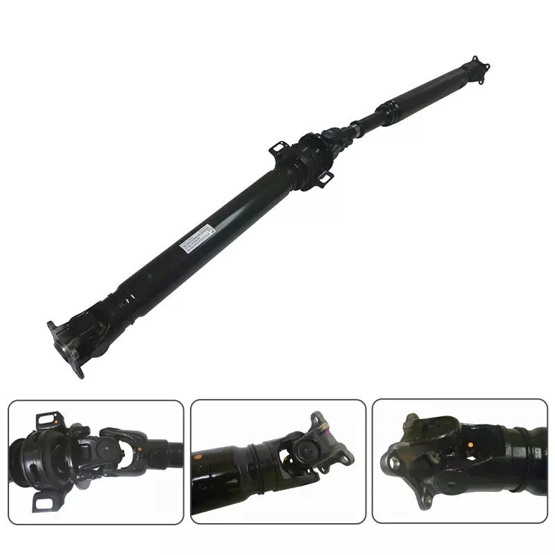
Can you explain the components and function of a PTO drive shaft system?
A PTO (Power Take-Off) drive shaft system consists of several components that work together to transfer power from a primary power source, such as a tractor or engine, to various implements or machinery. Each component plays a specific role in ensuring the efficient and reliable transmission of rotational power. Here’s a detailed explanation of the components and their functions within a PTO drive shaft system:
1. Primary Power Source:
The primary power source is typically a tractor or engine equipped with a PTO output shaft. This shaft generates rotational power from the engine’s crankshaft or transmission, acting as the starting point for power transmission.
2. PTO Output Shaft:
The PTO output shaft is a rotating shaft located on the primary power source, specifically designed to transfer power to external devices. It is typically located at the rear of a tractor and may have various spline configurations to accommodate different types of PTO drive shafts.
3. PTO Drive Shaft:
The PTO drive shaft is the main component of the system, responsible for transmitting power from the primary power source to the implement or machinery. It consists of a rotating shaft with splines at both ends. One end connects to the PTO output shaft, while the other end connects to the input shaft of the implement. The drive shaft rotates at the same speed as the primary power source, effectively delivering power to the implement.
4. Splined Connections:
The splined connections on the PTO drive shaft and the PTO output shaft of the primary power source provide a secure and robust connection. These splines ensure proper alignment and torque transmission between the two shafts, enabling efficient power transfer while accommodating varying distances and alignments.
5. Safety Guards and Shields:
PTO drive shaft systems often incorporate safety guards and shields to protect operators from potential hazards associated with rotating components. These guards and shields cover the rotating parts of the drive shaft, reducing the risk of entanglement or contact during operation.
6. Telescoping or Sliding Mechanism:
Some PTO drive shafts feature a telescoping or sliding mechanism. This allows the drive shaft to be adjusted in length, accommodating different distances between the primary power source and the implement. The telescoping or sliding mechanism ensures proper alignment and prevents excessive tension or binding of the drive shaft.
7. Shear Pins or Clutch Mechanism:
To protect the PTO drive shaft and the machinery from excessive loads or sudden shocks, shear pins or a clutch mechanism may be incorporated. These safety features are designed to disconnect the drive shaft from the primary power source in the event of an overload or sudden impact, preventing damage to the drive shaft and associated equipment.
8. Maintenance and Lubrication Points:
PTO drive shaft systems require regular maintenance and lubrication to ensure optimal performance and longevity. Lubrication points are typically provided to allow for the application of grease or oil to reduce friction and wear. Regular inspections and maintenance help identify any issues or wear in the components, ensuring safe and efficient operation.
9. Implement Input Shaft:
The implement input shaft is the counterpart to the PTO drive shaft on the implement or machinery side. It connects to the PTO drive shaft and receives power for driving the specific machinery or performing various tasks. The input shaft is precisely aligned with the drive shaft to ensure efficient power transfer.
In summary, a PTO drive shaft system consists of components such as the primary power source, PTO output shaft, PTO drive shaft, splined connections, safety guards, telescoping or sliding mechanisms, shear pins or clutch mechanisms, maintenance and lubrication points, and the implement input shaft. Together, these components enable the efficient and reliable transfer of rotational power from the primary power source to the implement or machinery, allowing for a wide range of tasks and applications in agricultural and industrial settings.


editor by CX 2024-04-13

























