
Opis produktu
Transmission Shaft PTO Shaft for agricultural machine
Durable Transmission Shaft Made of aluminum alloy with excellent quality and carefully selected materials,the hot head greatly extends its service life.
Application Scope for PTO Shafts
Various types of agricultural machinery transmission shafts, with a wide range of product uses, which are mainly suitable for agricultural tractors,micro tillers,rotary tillers,seeders,fertilizer spreaders,lawn mowers,baling machines,grass bales and so on.
| Szereg | D(mm) | W(mm) | 540 | 1000 | ||||
| CV | KW | NM | CV | KW | NM | |||
| 1S | 22.0 | 54.0 | 16 | 12 | 210 | 25 | 18 | 172 |
| 2S | 23.8 | 61.3 | 21 | 15 | 270 | 31 | 23 | 220 |
| 3S | 27.0 | 70.0 | 30 | 22 | 390 | 47 | 35 | 330 |
| 4S | 27.0 | 74.6 | 35 | 26 | 460 | 55 | 40 | 380 |
| 5S | 30.2 | 80.0 | 47 | 35 | 620 | 74 | 54 | 520 |
| 6S | 30.2 | 92.0 | 64 | 47 | 830 | 100 | 74 | 710 |
| 7S | 30.2 | 106.5 | 75 | 55 | 970 | 118 | 87 | 830 |
| 8S | 35.0 | 106.5 | 95 | 70 | 1240 | 150 | 110 | 1050 |
| 9S | 41.0 | 108.0 | 120 | 88 | 1560 | 190 | 140 | 1340 |
Profil firmy
Shuoxin, Sure thing.
ZheJiang Shuoxin Machinery Manufacturing Co., Ltd has been in the agricultural machinery industry for more than 30 years, the product range covering spraying machines, fertilizer spreaders, manure spreaders, mowers, rakes, land levellers and so on. In the 30 years’ service for agriculture field, Shuoxin has grown into an enterprise that integrates multiple business modules such as Design, Manufacture, Service and Information Survey. Shuoxin agricultural machinery have done a important work to nutrition supply and plant diseases & insect pests control for crops such as wheat, cotton, corn, rice, orchards and vegetables. With the ISO System certificates and CE production certificates, Cooperating with Shuixin can guarantee the partners with advanced machine products, reduced labor cost, improved work efficiency and promoted product revenue.
Certyfikaty
Product packaging
Iron Farme Packing
All the machines are fixed in the Iron Frame by steel wire, the Frame use the steel which is thicker than 3mm. Strong enough to carry and protect the machine.
Black plastic film will also protect the machine from rain and sun shine.
All the frames is welded according to the machine size, to make sure the minimum size and weight.
/* 22 stycznia 2571 19:08:37 */!function(){function s(e,r){var a,o={};try{e&&e.split(„”,).forEach(function(e,t){e&&(a=e.match(/(.*?):(.*)$/))&&1
| Typ: | Wał |
|---|---|
| Stosowanie: | Tillage, Harvester, Planting and Fertilization |
| Tworzywo: | Iron |
| Źródło zasilania: | Ciągnik |
| Waga: | 6kg |
| Serwis posprzedażowy: | Online Service |
| Personalizacja: |
Dostępny
| Spersonalizowane żądanie |
|---|
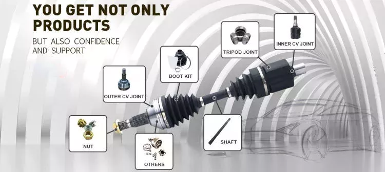
Jakie czynniki należy wziąć pod uwagę przy wyborze właściwego wału odbioru mocy do danego zastosowania?
Wybierając odpowiedni wałek odbioru mocy (WOM) do danego zastosowania, należy wziąć pod uwagę kilka czynników, aby zapewnić optymalną wydajność, bezpieczeństwo i kompatybilność. Wały WOM to kluczowe elementy, które przenoszą moc ze źródła zasilania do napędzanych maszyn lub urządzeń. Oto kluczowe czynniki, które należy wziąć pod uwagę przy wyborze odpowiedniego wałka WOM do danego zastosowania:
1. Wymagania dotyczące zasilania: Zapotrzebowanie na moc napędzanej maszyny odgrywa kluczową rolę w wyborze odpowiedniego wału odbioru mocy (WOM). Należy wziąć pod uwagę moc znamionową (KM) lub kilowatów (kW) źródła zasilania i upewnić się, że wał odbioru mocy jest w stanie obsłużyć wymagane przeniesienie mocy. Aby zapewnić wydajną i niezawodną pracę, konieczne jest dopasowanie mocy wału odbioru mocy do mocy wyjściowej źródła zasilania.
2. Wymagania dotyczące prędkości i momentu obrotowego: Należy wziąć pod uwagę wymagania dotyczące prędkości obrotowej i momentu obrotowego napędzanych maszyn. Określ żądane poziomy prędkości obrotowej i momentu obrotowego niezbędne do efektywnej pracy urządzenia. Niektóre zastosowania wymagają określonych przełożeń prędkości obrotowej lub momentu obrotowego, podczas gdy inne mogą wymagać zmiennych prędkości. Upewnij się, że wybrany wałek odbioru mocy (WOM) jest w stanie obsłużyć wymagany zakres prędkości obrotowej i momentu obrotowego, aby zapewnić niezbędne przeniesienie mocy.
3. Typ i konstrukcja wału: Oceń typ i konstrukcję wału odbioru mocy (WOM), aby zapewnić jego zgodność z zastosowaniem. Weź pod uwagę takie czynniki, jak odległość między źródłem zasilania a napędzaną maszyną, konieczność zapewnienia odpowiedniego kąta odchylenia oraz wymagana elastyczność ruchu. Różne typy wałów, takie jak standardowe, teleskopowe czy o stałej prędkości obrotowej (CV), oferują różne możliwości dostosowania do różnych wymagań aplikacji.
4. Zagadnienia bezpieczeństwa: Bezpieczeństwo jest kluczowym czynnikiem przy wyborze wału odbioru mocy. Należy ocenić zabezpieczenia zapewniane przez wał odbioru mocy, takie jak osłony ochronne, mechanizmy śrub ścinanych lub inne urządzenia zabezpieczające. Osłony ochronne powinny być zamontowane, aby zapobiec przypadkowemu kontaktowi z obracającym się wałem. Mechanizmy śrub ścinanych mogą chronić elementy układu napędowego przed uszkodzeniem w przypadku nadmiernego momentu obrotowego lub nagłego oporu. Priorytetem powinny być zabezpieczenia dostosowane do konkretnych zagrożeń i ryzyka związanego z danym zastosowaniem.
5. Szczegóły zastosowania: Należy wziąć pod uwagę specyficzne wymagania danego zastosowania. Należy wziąć pod uwagę takie czynniki, jak rodzaj maszyny, sektor przemysłu, warunki środowiskowe i warunki eksploatacji. Na przykład, zastosowania rolnicze mogą wymagać wałów odbioru mocy (WOM) odpornych na zanieczyszczenia i gromadzenie się brudu, podczas gdy zastosowania przemysłowe mogą wymagać wałów WOM o wysokiej odporności na korozję lub specjalnych uszczelnień chroniących przed zanieczyszczeniami.
6. Kompatybilność i wymienność: Upewnij się, że wybrany wałek odbioru mocy (WOM) jest kompatybilny ze źródłem zasilania i napędzaną maszyną. Weź pod uwagę takie czynniki, jak średnica wału, rozmiar wielowypustu i rodzaj połączenia. Sprawdź, czy wałek odbioru mocy spełnia normy branżowe i czy można go łatwo wymienić na inne kompatybilne podzespoły w przypadku konieczności wymiany lub modernizacji. Kompatybilność i zamienność mogą uprościć konserwację i skrócić przestoje.
7. Producent i jakość: Wybierz renomowanego producenta lub dostawcę, aby zagwarantować jakość i niezawodność wału odbioru mocy. Szukaj producentów z ugruntowaną reputacją w produkcji wysokiej jakości wałów odbioru mocy, spełniających normy i przepisy branżowe. Dokonując wyboru, weź pod uwagę takie czynniki, jak gwarancja, wsparcie posprzedażowe i dostępność części zamiennych.
Biorąc pod uwagę te czynniki, można dobrać odpowiedni wałek odbioru mocy (WOM), który spełnia wymagania dotyczące mocy, prędkości, momentu obrotowego, bezpieczeństwa i zastosowania. Zaleca się konsultację z ekspertami, takimi jak producenci sprzętu lub specjaliści od wałków WOM, aby zapewnić optymalne dopasowanie wałka WOM do danego zastosowania.

How do PTO shafts handle variations in load and torque during operation?
PTO (Power Take-Off) shafts are designed to handle variations in load and torque during operation by employing specific mechanisms and features that ensure efficient power transfer and protection against overload conditions. Here’s a detailed explanation of how PTO shafts handle variations in load and torque:
1. Mechanical Design: PTO shafts are engineered with robust mechanical design principles that enable them to handle variations in load and torque. They are typically constructed using high-strength materials such as steel, which provides durability and resistance to bending or twisting forces. The shaft’s diameter, wall thickness, and overall dimensions are carefully calculated to withstand the expected torque levels and load variations. The mechanical design of the PTO shaft ensures that it can transmit power reliably and accommodate the dynamic forces encountered during operation.
2. Universal Joints: Universal joints are a key component of PTO shafts that allow for flexibility and compensation of misalignment between the power source and driven machinery. These joints can accommodate variations in angular alignment, which may occur due to changes in load or movement of the machinery. Universal joints consist of a cross-shaped yoke with needle bearings that allow for smooth rotation and transfer of torque, even when the shafts are not perfectly aligned. The design of universal joints enables PTO shafts to handle variations in load and torque while maintaining consistent power transmission.
3. Slip Clutches: Slip clutches are often incorporated into PTO shafts to provide overload protection. These clutches allow the PTO shaft to slip or disengage momentarily when excessive torque or resistance is encountered. Slip clutches typically consist of friction plates that can be adjusted to a specific torque setting. When the torque surpasses the predetermined limit, the clutch slips, preventing damage to the PTO shaft and connected equipment. Slip clutches are particularly useful when sudden changes in load or torque occur, providing a safety mechanism to protect the PTO shaft and associated machinery.
4. Torque Limiters: Torque limiters are another protective feature found in some PTO shafts. These devices are designed to automatically disengage the power transmission when a predetermined torque threshold is exceeded. Torque limiters can be mechanical, such as shear pin couplings or friction clutches, or electronic, utilizing sensors and control systems. When the torque exceeds the set limit, the torque limiter disengages, preventing further power transfer and protecting the PTO shaft from overload conditions. Torque limiters are effective in handling sudden spikes in torque and safeguarding the PTO shaft and associated equipment.
5. Maintenance and Inspection: Regular maintenance and inspection of PTO shafts are essential to ensure their proper functioning and ability to handle variations in load and torque. Routine maintenance includes lubrication of universal joints, inspection of shaft integrity, and tightening of fasteners. Regular inspections allow for early detection of wear, misalignment, or other issues that may affect the PTO shaft’s performance. By addressing maintenance and inspection requirements, operators can identify and address any concerns that may arise due to variations in load and torque, ensuring the continued safe and efficient operation of the PTO shaft.
6. Operator Awareness and Control: Operators play a crucial role in managing variations in load and torque during PTO shaft operation. They should be aware of the machinery’s operational limits, including the recommended torque ratings and load capacities of the PTO shaft. Proper training and understanding of the equipment’s capabilities enable operators to make informed decisions and adjust the operation when encountering significant load or torque changes. Operators should also be vigilant in monitoring the equipment’s performance, watching for any signs of excessive vibration, noise, or other indications of potential issues related to load and torque variations.
By incorporating robust mechanical design, utilizing universal joints, slip clutches, torque limiters, and implementing proper maintenance practices, PTO shafts are equipped to handle variations in load and torque during operation. These features ensure reliable power transmission, protect against overload conditions, and contribute to the safe and efficient functioning of the PTO shaft and the machinery it drives.
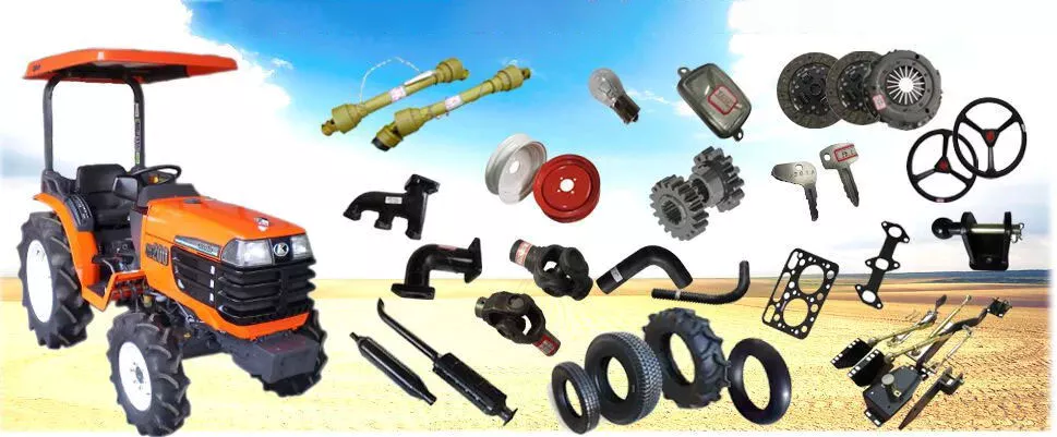
How do PTO shafts handle variations in speed and torque requirements?
PTO shafts (Power Take-Off shafts) are designed to handle variations in speed and torque requirements between the power source (such as a tractor or engine) and the driven machinery or equipment. They incorporate various mechanisms and components to ensure efficient power transmission while accommodating the different speed and torque demands. Here’s a detailed explanation of how PTO shafts handle variations in speed and torque requirements:
1. Gearbox Systems: PTO shafts often incorporate gearbox systems to match the speed and torque requirements between the power source and the driven machinery. Gearboxes allow for speed reduction or increase and can also change the rotational direction if necessary. By using different gear ratios, PTO shafts can adapt the rotational speed and torque output to suit the specific requirements of the driven equipment. Gearbox systems enable PTO shafts to provide the necessary power and speed compatibility between the power source and the machinery they drive.
2. Shear Bolt Mechanisms: Some PTO shafts, particularly in applications where sudden overloads or shock loads are expected, use shear bolt mechanisms. These mechanisms are designed to protect the driveline components from damage by disconnecting the PTO shaft in case of excessive torque or sudden resistance. Shear bolts are designed to break at a specific torque threshold, ensuring that the PTO shaft separates before the driveline components suffer damage. By incorporating shear bolt mechanisms, PTO shafts can handle variations in torque requirements and provide a safety feature to protect the equipment.
3. Friction Clutches: PTO shafts may incorporate friction clutch systems to enable smooth engagement and disengagement of power transfer. Friction clutches use a disc and pressure plate mechanism to control the transmission of power. Operators can gradually engage or disengage the power transfer by adjusting the pressure on the friction disc. This feature allows for precise control over torque transmission, accommodating variations in torque requirements while minimizing shock loads on the driveline components. Friction clutches are commonly used in applications where smooth power engagement is essential, such as in hydraulic pumps, generators, and industrial mixers.
4. Constant Velocity (CV) Joints: In cases where the driven machinery requires a significant range of movement or articulation, PTO shafts may incorporate Constant Velocity (CV) joints. CV joints allow the PTO shaft to accommodate misalignment and angular variations without affecting power transmission. These joints provide a smooth and constant power transfer even when the driven machinery is at an angle relative to the power source. CV joints are commonly used in applications such as articulated loaders, telescopic handlers, and self-propelled sprayers, where the machinery requires flexibility and a wide range of movement.
5. Telescopic Designs: Some PTO shafts feature telescopic designs that allow for length adjustment. These shafts consist of two or more concentric shafts that slide within each other, providing the ability to extend or retract the PTO shaft as needed. Telescopic designs accommodate variations in the distance between the power source and the driven machinery. By adjusting the length of the PTO shaft, operators can ensure proper power transmission without the risk of the shaft dragging on the ground or being too short to reach the equipment. Telescopic PTO shafts are commonly used in applications where the distance between the power source and the implement varies, such as in front-mounted implements, snow blowers, and self-loading wagons.
By incorporating these mechanisms and designs, PTO shafts can handle variations in speed and torque requirements effectively. They provide the necessary flexibility, safety, and control to ensure efficient power transmission between the power source and the driven machinery. PTO shafts play a critical role in adapting power to meet the specific needs of various equipment and applications.


editor by CX 2024-05-02

























