
Penerangan Produk
Product Overview
Planetary Concrete Mixer
MP series planetary concrete mixer used for mixing concrete .It is not only applies in common concrete ,precast concrete but also in high performance concrete. Planetary Concrete Mixers widely apply to produce precast concrete, common commercial concrete and high performance concrete.
It is suitable for mixing dry hard concrete (roller compacted concrete). It is widely used in the production of building blocks and prefabricated parts, and also can be used to produce of steel fiber reinforced concrete, color concrete and dry mortar, etc.
We also could customize observing door, skip hopper, extended funnel with bag breaker for bag, cement weighting device and water metering device according to customers’ requirement.
FEATURES AT A GLANCE
Our Advantage
Customized service:Unique top opening design.Position and size of the feeding inlet according to the customer’s needs.
Capacity :50L~1500L
♦Durable chill cast wear sleeves and paddles
♦Hard wearing chill cast tiles for wall and floor
♦Heavy duty discharge door mechanisms
♦Spring tensioned mixing arms for safety
♦Motor and gearbox are located on top of the mixer for easy cleaning and maintenance
Full Process Solution Provider of SDCAD
MP50 MP250 MP500
MP750 MP1000 MP2000
SDCADI Planetary Mixer Features
* Optimum Homogenization of mixing materials.
* Adopt special high-strength, high-reliability planetary reducer with patent.
* Simple Structure, Simple and Convenient Maintenance.
* Flexible Layout, 1-3 unloading doors are optional for different production lines.
* Dustproof movable covers assisted by gas springs.
* Interlocking device and safety switch on every movable cover.
* Interchangeable wear-resistant liners with counter sunk fixing bolts.
* All on-board engineering is protected in PVC-coated metal conduits and connected to a heavy-duty aluminum junction box.
PRODUCT CONFIGURATION
Mixing Locus Diagrams
This diagrams show the perfect mixing action of the SDCAD planetary mixer from 5 to 60 seconds after material is added. Note that the floor is completely swept by the mixing stars action every 4 revolutions (6 seconds) and that each zone is covered at regular intervals in time.
Reduction Gearbox Maintenance Access Mixing Device
The hydraulic power unit Hydraulic Unit Water spray pipe
Mixing Pan with Wear Linings
SDCAD Planetary mixer is meticulously engineered with high-strength structural steel and durable wear-resistant CZPT plates.Our planetary mixer achieves a stringent control of the roundness and flatness error of the mixing drum, ensuring a maximum deviation of only 2-3mm for pristine discharge.
The CZPT plates of our planetary mixer are carefully selected to cater to the specific mixing requirements of diverse raw materials. These include high-chromium alloy cast, PE polymer,
surfacing, stainless steel, and other suitable options, depending on the specific raw materials to be mixed.
PRODUCT SPECIFICATIONS
|
Model |
MP330 |
MP500 |
MP750 |
MP1000 |
MP1500 |
MP2000 |
MP2500 |
MP3000 |
|
Output Capacity (L) |
330 |
500 |
750 |
1000 |
1500 |
2000 |
2500 |
3000 |
|
Input Capacity (L) |
500 |
750 |
1125 |
1500 |
2250 |
3000 |
3750 |
4500 |
|
Input Mass (kg) |
800 |
1200 |
1800 |
2400 |
3600 |
4800 |
6000 |
7200 |
|
Mixing Power (kw) |
15 |
18.5 |
30 |
37 |
55 |
75 |
90 |
110 |
|
Discharge Power (kw) |
2.2 |
2.2 |
2.2 |
3 |
3 |
4 |
4 |
4 |
|
Lifting Power (kw) |
4 |
4 |
7.5 |
11 |
15 |
22 |
— |
— |
|
Skipper Capacity (L) |
580 |
870 |
1300 |
1740 |
2610 |
3480 |
— |
— |
|
Skipper Mass (kg) |
870 |
1305 |
1950 |
2610 |
3615 |
5220 |
— |
— |
|
Skipper Speed (m/s) |
0.25 |
0.25 |
0.25 |
0.25 |
0.25 |
0.25 |
— |
— |
|
Weight (kg) |
1700 |
2000 |
3500 |
6000 |
7000 |
8500 |
10500 |
11000 |
|
Dimension (mm) |
1910 * 1590* 1747 |
2220* 2071* 1880 |
2581* 2336 * 2195 |
2891* 2602* 2217 |
3223* 2902* 2425 |
3625*3230* 2630 |
2893* 3550* 2695 |
3893* 3550* 2975 |
Packaging and Transportation
Perkhidmatan Kami
1.According to your inquiry, We will reply to you in 24 hours.
2.Best After-sales: We will send the technical personnel to the site for installation, commissioning and training work.
3.Warranty period 12 Months, in addition to the force majeure and man-made factors, the damage caused by design, process and manufacturing equipment, the seller is responsible for sending people to offer free repair.
4.We will send the spare parts as soon as possible when necessary, equipment repair parts provided by the seller are original,authentic, quality goods.
Industry Application
Successful Project
SALES AND SERVICE NETWORKSIMILAR PRODUCTS
/* 22 Januari 2571 19:08:37 */!function(){function s(e,r){var a,o={};try{e&&e.split(“,”).forEach(function(e,t){e&&(a=e.match(/(.*?):(.*)$/)&
| Perkhidmatan selepas jualan: | Provide a Complete Installation and Operation Manu |
|---|---|
| Waranti: | One Year |
| Jenis: | Concrete Mixer |
| Shotcrete Type: | Dry |
| Machining Process: | Welded Molding Machine |
| Structure: | Rotor Type |
| Penyesuaian: |
Tersedia
| Permintaan Tersuai |
|---|

How do manufacturers ensure the compatibility of drive shafts with different equipment?
Manufacturers employ various strategies and processes to ensure the compatibility of drive shafts with different equipment. Compatibility refers to the ability of a drive shaft to effectively integrate and function within a specific piece of equipment or machinery. Manufacturers take into account several factors to ensure compatibility, including dimensional requirements, torque capacity, operating conditions, and specific application needs. Here’s a detailed explanation of how manufacturers ensure the compatibility of drive shafts:
1. Application Analysis:
Manufacturers begin by conducting a thorough analysis of the intended application and equipment requirements. This analysis involves understanding the specific torque and speed demands, operating conditions (such as temperature, vibration levels, and environmental factors), and any unique characteristics or constraints of the equipment. By gaining a comprehensive understanding of the application, manufacturers can tailor the design and specifications of the drive shaft to ensure compatibility.
2. Customization and Design:
Manufacturers often offer customization options to adapt drive shafts to different equipment. This customization involves tailoring the dimensions, materials, joint configurations, and other parameters to match the specific requirements of the equipment. By working closely with the equipment manufacturer or end-user, manufacturers can design drive shafts that align with the equipment’s mechanical interfaces, mounting points, available space, and other constraints. Customization ensures that the drive shaft fits seamlessly into the equipment, promoting compatibility and optimal performance.
3. Torque and Power Capacity:
Drive shaft manufacturers carefully determine the torque and power capacity of their products to ensure compatibility with different equipment. They consider factors such as the maximum torque requirements of the equipment, the expected operating conditions, and the safety margins necessary to withstand transient loads. By engineering drive shafts with appropriate torque ratings and power capacities, manufacturers ensure that the shaft can handle the demands of the equipment without experiencing premature failure or performance issues.
4. Material Selection:
Manufacturers choose materials for drive shafts based on the specific needs of different equipment. Factors such as torque capacity, operating temperature, corrosion resistance, and weight requirements influence material selection. Drive shafts may be made from various materials, including steel, aluminum alloys, or specialized composites, to provide the necessary strength, durability, and performance characteristics. The selected materials ensure compatibility with the equipment’s operating conditions, load requirements, and other environmental factors.
5. Joint Configurations:
Drive shafts incorporate joint configurations, such as universal joints (U-joints) or constant velocity (CV) joints, to accommodate different equipment needs. Manufacturers select and design the appropriate joint configuration based on factors such as operating angles, misalignment tolerances, and the desired level of smooth power transmission. The choice of joint configuration ensures that the drive shaft can effectively transmit power and accommodate the range of motion required by the equipment, promoting compatibility and reliable operation.
6. Quality Control and Testing:
Manufacturers implement stringent quality control processes and testing procedures to verify the compatibility of drive shafts with different equipment. These processes involve conducting dimensional inspections, material testing, torque and stress analysis, and performance testing under simulated operating conditions. By subjecting drive shafts to rigorous quality control measures, manufacturers can ensure that they meet the required specifications and performance criteria, guaranteeing compatibility with the intended equipment.
7. Pematuhan dengan Piawaian:
Manufacturers ensure that their drive shafts comply with relevant industry standards and regulations. Compliance with standards, such as ISO (International Organization for Standardization) or specific industry standards, provides assurance of quality, safety, and compatibility. Adhering to these standards helps manufacturers meet the expectations and requirements of equipment manufacturers and end-users, ensuring that the drive shafts are compatible and can be seamlessly integrated into different equipment.
8. Collaboration and Feedback:
Manufacturers often collaborate closely with equipment manufacturers, OEMs (Original Equipment Manufacturers), or end-users to gather feedback and incorporate their specific requirements into the drive shaft design and manufacturing processes. This collaborative approach ensures that the drive shafts are compatible with the intended equipment and meet the expectations of the end-users. By actively seeking input and feedback, manufacturers can continuously improve their products’ compatibility and performance.
In summary, manufacturers ensure the compatibility of drive shafts with different equipment through a combination of application analysis, customization, torque and power capacity considerations, material selection, joint configurations, quality control and testing, compliance with standards, and collaboration with equipment manufacturers and end-users. These efforts enable manufacturers to design and produce drive shafts that seamlessly integrate with various equipment, ensuring optimal performance, reliability, and compatibility in different applications.
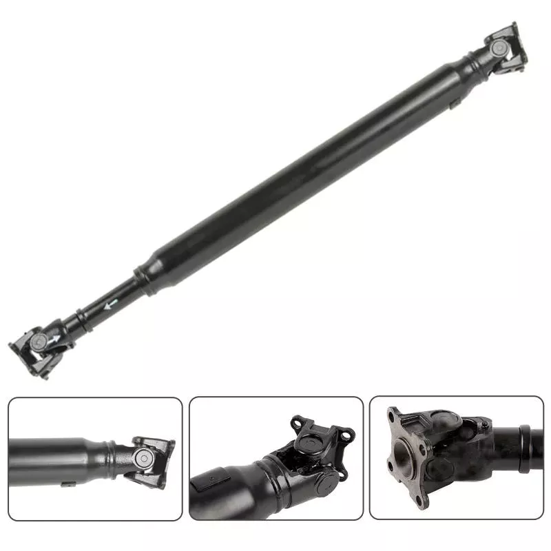
Can drive shafts be customized for specific vehicle or equipment requirements?
Yes, drive shafts can be customized to meet specific vehicle or equipment requirements. Customization allows manufacturers to tailor the design, dimensions, materials, and other parameters of the drive shaft to ensure compatibility and optimal performance within a particular vehicle or equipment. Here’s a detailed explanation of how drive shafts can be customized:
1. Dimensional Customization:
Drive shafts can be customized to match the dimensional requirements of the vehicle or equipment. This includes adjusting the overall length, diameter, and spline configuration to ensure proper fitment and clearances within the specific application. By customizing the dimensions, the drive shaft can be seamlessly integrated into the driveline system without any interference or limitations.
2. Material Selection:
The choice of materials for drive shafts can be customized based on the specific requirements of the vehicle or equipment. Different materials, such as steel alloys, aluminum alloys, or specialized composites, can be selected to optimize strength, weight, and durability. The material selection can be tailored to meet the torque, speed, and operating conditions of the application, ensuring the drive shaft’s reliability and longevity.
3. Joint Configuration:
Drive shafts can be customized with different joint configurations to accommodate specific vehicle or equipment requirements. For example, universal joints (U-joints) may be suitable for applications with lower operating angles and moderate torque demands, while constant velocity (CV) joints are often used in applications requiring higher operating angles and smoother power transmission. The choice of joint configuration depends on factors such as operating angle, torque capacity, and desired performance characteristics.
4. Torque and Power Capacity:
Customization allows drive shafts to be designed with the appropriate torque and power capacity for the specific vehicle or equipment. Manufacturers can analyze the torque requirements, operating conditions, and safety margins of the application to determine the optimal torque rating and power capacity of the drive shaft. This ensures that the drive shaft can handle the required loads without experiencing premature failure or performance issues.
5. Balancing and Vibration Control:
Drive shafts can be customized with precision balancing and vibration control measures. Imbalances in the drive shaft can lead to vibrations, increased wear, and potential driveline issues. By employing dynamic balancing techniques during the manufacturing process, manufacturers can minimize vibrations and ensure smooth operation. Additionally, vibration dampers or isolation systems can be integrated into the drive shaft design to further mitigate vibrations and enhance overall system performance.
6. Integration and Mounting Considerations:
Customization of drive shafts takes into account the integration and mounting requirements of the specific vehicle or equipment. Manufacturers work closely with the vehicle or equipment designers to ensure that the drive shaft fits seamlessly into the driveline system. This includes adapting the mounting points, interfaces, and clearances to ensure proper alignment and installation of the drive shaft within the vehicle or equipment.
7. Collaboration and Feedback:
Manufacturers often collaborate with vehicle manufacturers, OEMs (Original Equipment Manufacturers), or end-users to gather feedback and incorporate their specific requirements into the drive shaft customization process. By actively seeking input and feedback, manufacturers can address specific needs, optimize performance, and ensure compatibility with the vehicle or equipment. This collaborative approach enhances the customization process and results in drive shafts that meet the exact requirements of the application.
8. Compliance with Standards:
Customized drive shafts can be designed to comply with relevant industry standards and regulations. Compliance with standards, such as ISO (International Organization for Standardization) or specific industry standards, ensures that the customized drive shafts meet quality, safety, and performance requirements. Adhering to these standards provides assurance that the drive shafts are compatible and can be seamlessly integrated into the specific vehicle or equipment.
In summary, drive shafts can be customized to meet specific vehicle or equipment requirements through dimensional customization, material selection, joint configuration, torque and power capacity optimization, balancing and vibration control, integration and mounting considerations, collaboration with stakeholders, and compliance with industry standards. Customization allows drive shafts to be precisely tailored to the needs of the application, ensuring compatibility, reliability, and optimal performance.
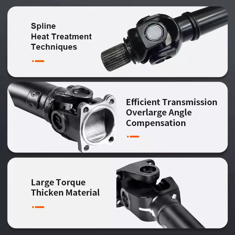
Bagaimanakah aci pemacu menyumbang kepada pemindahan kuasa putaran dalam pelbagai aplikasi?
Aci pacu memainkan peranan penting dalam memindahkan kuasa putaran dari enjin atau sumber kuasa ke roda atau komponen yang digerakkan dalam pelbagai aplikasi. Sama ada dalam kenderaan atau jentera, aci pacu membolehkan penghantaran kuasa yang cekap dan memudahkan fungsi sistem yang berbeza. Berikut ialah penjelasan terperinci tentang bagaimana aci pacu menyumbang kepada pemindahan kuasa putaran:
1. Aplikasi Kenderaan:
Dalam kenderaan, aci pacu bertanggungjawab untuk menghantar kuasa putaran dari enjin ke roda, membolehkan kenderaan bergerak. Aci pacu menghubungkan kotak gear atau aci output transmisi ke pembezaan, yang seterusnya mengagihkan kuasa ke roda. Apabila enjin menjana tork, ia dipindahkan melalui aci pacu ke roda, mendorong kenderaan ke hadapan. Pemindahan kuasa ini membolehkan kenderaan memecut, mengekalkan kelajuan dan mengatasi rintangan, seperti geseran dan cerun.
2. Aplikasi Jentera:
Dalam jentera, aci pacu digunakan untuk memindahkan kuasa putaran dari enjin atau motor ke pelbagai komponen pemacu. Contohnya, dalam jentera perindustrian, aci pacu boleh digunakan untuk menghantar kuasa ke pam, penjana, penghantar atau sistem mekanikal lain. Dalam jentera pertanian, aci pacu biasanya digunakan untuk menyambungkan sumber kuasa ke peralatan seperti mesin penuai, mesin pembalut atau sistem pengairan. Aci pacu membolehkan mesin ini melaksanakan fungsi yang dimaksudkan dengan menghantar kuasa putaran kepada komponen yang diperlukan.
3. Penghantaran Kuasa:
Aci pemacu direka bentuk untuk menghantar kuasa putaran dengan cekap dan andal. Ia mampu memindahkan sejumlah besar tork dari enjin ke roda atau komponen yang digerakkan. Tork yang dihasilkan oleh enjin dihantar melalui aci pemacu tanpa kehilangan kuasa yang ketara. Dengan mengekalkan sambungan yang tegar antara enjin dan komponen yang digerakkan, aci pemacu memastikan bahawa kuasa yang dihasilkan oleh enjin digunakan secara berkesan dalam melaksanakan kerja yang berguna.
4. Gandingan Fleksibel:
Salah satu fungsi utama aci pemacu adalah untuk menyediakan gandingan fleksibel antara enjin/transmisi dan roda atau komponen yang dipacu. Fleksibiliti ini membolehkan aci pemacu menampung pergerakan sudut dan mengimbangi ketidaksejajaran antara enjin dan sistem yang dipacu. Dalam kenderaan, apabila sistem gantungan bergerak atau roda menghadapi rupa bumi yang tidak rata, aci pemacu melaraskan panjang dan sudutnya untuk mengekalkan pemindahan kuasa yang berterusan. Fleksibiliti ini membantu mencegah tekanan berlebihan pada komponen drivetrain dan memastikan penghantaran kuasa yang lancar.
5. Tork dan Kelajuan Penghantaran:
Aci pemacu bertanggungjawab untuk menghantar kedua-dua tork dan kelajuan putaran. Tork ialah daya putaran yang dijana oleh enjin atau sumber kuasa, manakala kelajuan putaran ialah bilangan pusingan seminit (RPM). Aci pemacu mesti mampu mengendalikan keperluan tork aplikasi tanpa putaran atau lenturan yang berlebihan. Di samping itu, ia perlu mengekalkan kelajuan putaran yang diingini untuk memastikan komponen pemacu berfungsi dengan betul. Reka bentuk yang betul, pemilihan bahan dan pengimbangan aci pemacu menyumbang kepada penghantaran tork dan kelajuan yang cekap.
6. Panjang dan Imbangan:
Panjang dan keseimbangan aci pemacu adalah faktor kritikal dalam prestasinya. Panjang aci pemacu ditentukan oleh jarak antara enjin atau sumber kuasa dan komponen yang digerakkan. Saiznya hendaklah sesuai untuk mengelakkan getaran atau lenturan yang berlebihan. Aci pemacu diseimbangkan dengan teliti untuk meminimumkan getaran dan ketidakseimbangan putaran, yang boleh menjejaskan prestasi keseluruhan, keselesaan dan jangka hayat sistem rangkaian pemacu.
7. Keselamatan dan Penyelenggaraan:
Aci pacu memerlukan langkah keselamatan yang betul dan penyelenggaraan berkala. Dalam kenderaan, aci pacu sering disertakan dalam tiub atau perumah pelindung untuk mengelakkan sentuhan dengan bahagian yang bergerak, sekali gus mengurangkan risiko kecederaan. Perisai atau pelindung keselamatan juga boleh dipasang di sekitar aci pacu yang terdedah dalam jentera untuk melindungi pengendali daripada potensi bahaya. Penyelenggaraan berkala termasuk memeriksa aci pacu untuk haus, kerosakan atau ketidaksejajaran, dan memastikan pelinciran sendi-U yang betul. Langkah-langkah ini membantu mencegah kegagalan, memastikan prestasi optimum dan memanjangkan hayat perkhidmatan aci pacu.
Secara ringkasnya, aci pacu memainkan peranan penting dalam memindahkan kuasa putaran dalam pelbagai aplikasi. Sama ada dalam kenderaan atau jentera, aci pacu membolehkan penghantaran kuasa yang cekap dari enjin atau sumber kuasa ke roda atau komponen yang digerakkan. Ia menyediakan gandingan fleksibel, mengendalikan transmisi tork dan kelajuan, menampung pergerakan sudut dan menyumbang kepada keselamatan dan penyelenggaraan sistem. Dengan memindahkan kuasa putaran secara berkesan, aci pacu memudahkan fungsi dan prestasi kenderaan dan jentera dalam pelbagai industri.


editor by CX 2024-05-10

























