
وصف المنتج
Product Overview
Planetary Concrete Mixer
MP series planetary concrete mixer used for mixing concrete .It is not only applies in common concrete ,precast concrete but also in high performance concrete. Planetary Concrete Mixers widely apply to produce precast concrete, common commercial concrete and high performance concrete.
It is suitable for mixing dry hard concrete (roller compacted concrete). It is widely used in the production of building blocks and prefabricated parts, and also can be used to produce of steel fiber reinforced concrete, color concrete and dry mortar, etc.
We also could customize observing door, skip hopper, extended funnel with bag breaker for bag, cement weighting device and water metering device according to customers’ requirement.
FEATURES AT A GLANCE
Our Advantage
Customized service:Unique top opening design.Position and size of the feeding inlet according to the customer’s needs.
Capacity :50L~1500L
♦Durable chill cast wear sleeves and paddles
♦Hard wearing chill cast tiles for wall and floor
♦Heavy duty discharge door mechanisms
♦Spring tensioned mixing arms for safety
♦Motor and gearbox are located on top of the mixer for easy cleaning and maintenance
Full Process Solution Provider of SDCAD
MP50 MP250 MP500
MP750 MP1000 MP2000
SDCADI Planetary Mixer Features
* Optimum Homogenization of mixing materials.
* Adopt special high-strength, high-reliability planetary reducer with patent.
* Simple Structure, Simple and Convenient Maintenance.
* Flexible Layout, 1-3 unloading doors are optional for different production lines.
* Dustproof movable covers assisted by gas springs.
* Interlocking device and safety switch on every movable cover.
* Interchangeable wear-resistant liners with counter sunk fixing bolts.
* All on-board engineering is protected in PVC-coated metal conduits and connected to a heavy-duty aluminum junction box.
PRODUCT CONFIGURATION
Mixing Locus Diagrams
This diagrams show the perfect mixing action of the SDCAD planetary mixer from 5 to 60 seconds after material is added. Note that the floor is completely swept by the mixing stars action every 4 revolutions (6 seconds) and that each zone is covered at regular intervals in time.
Reduction Gearbox Maintenance Access Mixing Device
The hydraulic power unit Hydraulic Unit Water spray pipe
Mixing Pan with Wear Linings
SDCAD Planetary mixer is meticulously engineered with high-strength structural steel and durable wear-resistant CZPT plates.Our planetary mixer achieves a stringent control of the roundness and flatness error of the mixing drum, ensuring a maximum deviation of only 2-3mm for pristine discharge.
The CZPT plates of our planetary mixer are carefully selected to cater to the specific mixing requirements of diverse raw materials. These include high-chromium alloy cast, PE polymer,
surfacing, stainless steel, and other suitable options, depending on the specific raw materials to be mixed.
PRODUCT SPECIFICATIONS
|
Model |
MP330 |
MP500 |
MP750 |
MP1000 |
MP1500 |
MP2000 |
MP2500 |
MP3000 |
|
Output Capacity (L) |
330 |
500 |
750 |
1000 |
1500 |
2000 |
2500 |
3000 |
|
Input Capacity (L) |
500 |
750 |
1125 |
1500 |
2250 |
3000 |
3750 |
4500 |
|
Input Mass (kg) |
800 |
1200 |
1800 |
2400 |
3600 |
4800 |
6000 |
7200 |
|
Mixing Power (kw) |
15 |
18.5 |
30 |
37 |
55 |
75 |
90 |
110 |
|
Discharge Power (kw) |
2.2 |
2.2 |
2.2 |
3 |
3 |
4 |
4 |
4 |
|
Lifting Power (kw) |
4 |
4 |
7.5 |
11 |
15 |
22 |
— |
— |
|
Skipper Capacity (L) |
580 |
870 |
1300 |
1740 |
2610 |
3480 |
— |
— |
|
Skipper Mass (kg) |
870 |
1305 |
1950 |
2610 |
3615 |
5220 |
— |
— |
|
Skipper Speed (m/s) |
0.25 |
0.25 |
0.25 |
0.25 |
0.25 |
0.25 |
— |
— |
|
Weight (kg) |
1700 |
2000 |
3500 |
6000 |
7000 |
8500 |
10500 |
11000 |
|
Dimension (mm) |
1910 * 1590* 1747 |
2220* 2071* 1880 |
2581* 2336 * 2195 |
2891* 2602* 2217 |
3223* 2902* 2425 |
3625*3230* 2630 |
2893* 3550* 2695 |
3893* 3550* 2975 |
Packaging and Transportation
خدماتنا
1.According to your inquiry, We will reply to you in 24 hours.
2.Best After-sales: We will send the technical personnel to the site for installation, commissioning and training work.
3.Warranty period 12 Months, in addition to the force majeure and man-made factors, the damage caused by design, process and manufacturing equipment, the seller is responsible for sending people to offer free repair.
4.We will send the spare parts as soon as possible when necessary, equipment repair parts provided by the seller are original,authentic, quality goods.
Industry Application
Successful Project
SALES AND SERVICE NETWORKSIMILAR PRODUCTS
/* 22 يناير 2571 19:08:37 */!function(){function s(e,r){var a,o={};try{e&&e.split(“,").forEach(function(e,t){e&&(a=e.match(/(.*?):(.*)$/))&&1
| خدمة ما بعد البيع: | Provide a Complete Installation and Operation Manu |
|---|---|
| ضمان: | One Year |
| يكتب: | Concrete Mixer |
| Shotcrete Type: | Dry |
| Machining Process: | Welded Molding Machine |
| Structure: | Rotor Type |
| التخصيص: |
متاح
| طلب مخصص |
|---|

How do manufacturers ensure the compatibility of drive shafts with different equipment?
Manufacturers employ various strategies and processes to ensure the compatibility of drive shafts with different equipment. Compatibility refers to the ability of a drive shaft to effectively integrate and function within a specific piece of equipment or machinery. Manufacturers take into account several factors to ensure compatibility, including dimensional requirements, torque capacity, operating conditions, and specific application needs. Here’s a detailed explanation of how manufacturers ensure the compatibility of drive shafts:
1. Application Analysis:
Manufacturers begin by conducting a thorough analysis of the intended application and equipment requirements. This analysis involves understanding the specific torque and speed demands, operating conditions (such as temperature, vibration levels, and environmental factors), and any unique characteristics or constraints of the equipment. By gaining a comprehensive understanding of the application, manufacturers can tailor the design and specifications of the drive shaft to ensure compatibility.
2. Customization and Design:
Manufacturers often offer customization options to adapt drive shafts to different equipment. This customization involves tailoring the dimensions, materials, joint configurations, and other parameters to match the specific requirements of the equipment. By working closely with the equipment manufacturer or end-user, manufacturers can design drive shafts that align with the equipment’s mechanical interfaces, mounting points, available space, and other constraints. Customization ensures that the drive shaft fits seamlessly into the equipment, promoting compatibility and optimal performance.
3. Torque and Power Capacity:
Drive shaft manufacturers carefully determine the torque and power capacity of their products to ensure compatibility with different equipment. They consider factors such as the maximum torque requirements of the equipment, the expected operating conditions, and the safety margins necessary to withstand transient loads. By engineering drive shafts with appropriate torque ratings and power capacities, manufacturers ensure that the shaft can handle the demands of the equipment without experiencing premature failure or performance issues.
4. Material Selection:
Manufacturers choose materials for drive shafts based on the specific needs of different equipment. Factors such as torque capacity, operating temperature, corrosion resistance, and weight requirements influence material selection. Drive shafts may be made from various materials, including steel, aluminum alloys, or specialized composites, to provide the necessary strength, durability, and performance characteristics. The selected materials ensure compatibility with the equipment’s operating conditions, load requirements, and other environmental factors.
5. Joint Configurations:
Drive shafts incorporate joint configurations, such as universal joints (U-joints) or constant velocity (CV) joints, to accommodate different equipment needs. Manufacturers select and design the appropriate joint configuration based on factors such as operating angles, misalignment tolerances, and the desired level of smooth power transmission. The choice of joint configuration ensures that the drive shaft can effectively transmit power and accommodate the range of motion required by the equipment, promoting compatibility and reliable operation.
6. Quality Control and Testing:
Manufacturers implement stringent quality control processes and testing procedures to verify the compatibility of drive shafts with different equipment. These processes involve conducting dimensional inspections, material testing, torque and stress analysis, and performance testing under simulated operating conditions. By subjecting drive shafts to rigorous quality control measures, manufacturers can ensure that they meet the required specifications and performance criteria, guaranteeing compatibility with the intended equipment.
7. Compliance with Standards:
Manufacturers ensure that their drive shafts comply with relevant industry standards and regulations. Compliance with standards, such as ISO (International Organization for Standardization) or specific industry standards, provides assurance of quality, safety, and compatibility. Adhering to these standards helps manufacturers meet the expectations and requirements of equipment manufacturers and end-users, ensuring that the drive shafts are compatible and can be seamlessly integrated into different equipment.
8. Collaboration and Feedback:
Manufacturers often collaborate closely with equipment manufacturers, OEMs (Original Equipment Manufacturers), or end-users to gather feedback and incorporate their specific requirements into the drive shaft design and manufacturing processes. This collaborative approach ensures that the drive shafts are compatible with the intended equipment and meet the expectations of the end-users. By actively seeking input and feedback, manufacturers can continuously improve their products’ compatibility and performance.
In summary, manufacturers ensure the compatibility of drive shafts with different equipment through a combination of application analysis, customization, torque and power capacity considerations, material selection, joint configurations, quality control and testing, compliance with standards, and collaboration with equipment manufacturers and end-users. These efforts enable manufacturers to design and produce drive shafts that seamlessly integrate with various equipment, ensuring optimal performance, reliability, and compatibility in different applications.
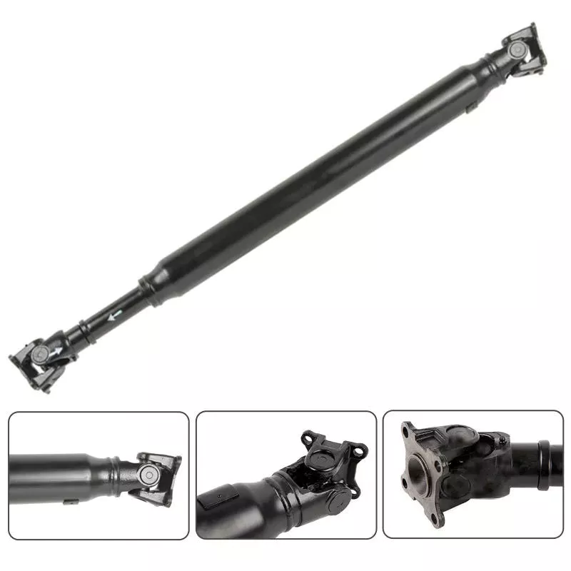
Can drive shafts be customized for specific vehicle or equipment requirements?
Yes, drive shafts can be customized to meet specific vehicle or equipment requirements. Customization allows manufacturers to tailor the design, dimensions, materials, and other parameters of the drive shaft to ensure compatibility and optimal performance within a particular vehicle or equipment. Here’s a detailed explanation of how drive shafts can be customized:
1. Dimensional Customization:
Drive shafts can be customized to match the dimensional requirements of the vehicle or equipment. This includes adjusting the overall length, diameter, and spline configuration to ensure proper fitment and clearances within the specific application. By customizing the dimensions, the drive shaft can be seamlessly integrated into the driveline system without any interference or limitations.
2. Material Selection:
The choice of materials for drive shafts can be customized based on the specific requirements of the vehicle or equipment. Different materials, such as steel alloys, aluminum alloys, or specialized composites, can be selected to optimize strength, weight, and durability. The material selection can be tailored to meet the torque, speed, and operating conditions of the application, ensuring the drive shaft’s reliability and longevity.
3. Joint Configuration:
Drive shafts can be customized with different joint configurations to accommodate specific vehicle or equipment requirements. For example, universal joints (U-joints) may be suitable for applications with lower operating angles and moderate torque demands, while constant velocity (CV) joints are often used in applications requiring higher operating angles and smoother power transmission. The choice of joint configuration depends on factors such as operating angle, torque capacity, and desired performance characteristics.
4. Torque and Power Capacity:
Customization allows drive shafts to be designed with the appropriate torque and power capacity for the specific vehicle or equipment. Manufacturers can analyze the torque requirements, operating conditions, and safety margins of the application to determine the optimal torque rating and power capacity of the drive shaft. This ensures that the drive shaft can handle the required loads without experiencing premature failure or performance issues.
5. Balancing and Vibration Control:
Drive shafts can be customized with precision balancing and vibration control measures. Imbalances in the drive shaft can lead to vibrations, increased wear, and potential driveline issues. By employing dynamic balancing techniques during the manufacturing process, manufacturers can minimize vibrations and ensure smooth operation. Additionally, vibration dampers or isolation systems can be integrated into the drive shaft design to further mitigate vibrations and enhance overall system performance.
6. Integration and Mounting Considerations:
Customization of drive shafts takes into account the integration and mounting requirements of the specific vehicle or equipment. Manufacturers work closely with the vehicle or equipment designers to ensure that the drive shaft fits seamlessly into the driveline system. This includes adapting the mounting points, interfaces, and clearances to ensure proper alignment and installation of the drive shaft within the vehicle or equipment.
7. Collaboration and Feedback:
Manufacturers often collaborate with vehicle manufacturers, OEMs (Original Equipment Manufacturers), or end-users to gather feedback and incorporate their specific requirements into the drive shaft customization process. By actively seeking input and feedback, manufacturers can address specific needs, optimize performance, and ensure compatibility with the vehicle or equipment. This collaborative approach enhances the customization process and results in drive shafts that meet the exact requirements of the application.
8. Compliance with Standards:
Customized drive shafts can be designed to comply with relevant industry standards and regulations. Compliance with standards, such as ISO (International Organization for Standardization) or specific industry standards, ensures that the customized drive shafts meet quality, safety, and performance requirements. Adhering to these standards provides assurance that the drive shafts are compatible and can be seamlessly integrated into the specific vehicle or equipment.
In summary, drive shafts can be customized to meet specific vehicle or equipment requirements through dimensional customization, material selection, joint configuration, torque and power capacity optimization, balancing and vibration control, integration and mounting considerations, collaboration with stakeholders, and compliance with industry standards. Customization allows drive shafts to be precisely tailored to the needs of the application, ensuring compatibility, reliability, and optimal performance.
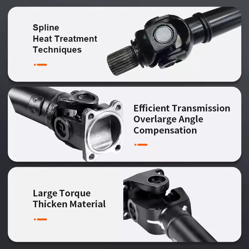
كيف تساهم أعمدة الدوران في نقل الطاقة الدورانية في التطبيقات المختلفة؟
تؤدي أعمدة نقل الحركة دورًا محوريًا في نقل الطاقة الدورانية من المحرك أو مصدر الطاقة إلى العجلات أو المكونات المُدارة في مختلف التطبيقات. سواءً في المركبات أو الآلات، تُمكّن أعمدة نقل الحركة من نقل الطاقة بكفاءة وتُسهّل عمل الأنظمة المختلفة. إليكم شرحًا مُفصّلًا لكيفية مساهمة أعمدة نقل الحركة في نقل الطاقة الدورانية:
1. تطبيقات المركبات:
في المركبات، تتولى أعمدة نقل الحركة مسؤولية نقل الطاقة الدورانية من المحرك إلى العجلات، مما يُمكّن المركبة من الحركة. يربط عمود نقل الحركة علبة التروس أو عمود خرج ناقل الحركة بالترس التفاضلي، الذي بدوره يوزع الطاقة على العجلات. عندما يُولّد المحرك عزم الدوران، ينتقل عبر عمود نقل الحركة إلى العجلات، دافعًا المركبة للأمام. يُمكّن نقل الطاقة هذا المركبة من التسارع، والحفاظ على السرعة، والتغلب على المقاومة، مثل الاحتكاك والمنحدرات.
2. تطبيقات الآلات:
في الآلات، تُستخدم أعمدة الدوران لنقل الطاقة الدورانية من المحرك إلى مختلف المكونات المُدارة. على سبيل المثال، في الآلات الصناعية، تُستخدم أعمدة الدوران لنقل الطاقة إلى المضخات والمولدات والناقلات وغيرها من الأنظمة الميكانيكية. أما في الآلات الزراعية، فتُستخدم أعمدة الدوران عادةً لتوصيل مصدر الطاقة بمعدات مثل الحصادات وآلات التجميع وأنظمة الري. تُمكّن أعمدة الدوران هذه الآلات من أداء وظائفها المطلوبة من خلال توصيل الطاقة الدورانية إلى المكونات اللازمة.
3. نقل الطاقة:
صُممت أعمدة نقل الحركة لنقل الطاقة الدورانية بكفاءة وموثوقية. وهي قادرة على نقل كميات كبيرة من عزم الدوران من المحرك إلى العجلات أو الأجزاء المُدارة. وينتقل عزم الدوران الناتج عن المحرك عبر عمود نقل الحركة دون فقدان كبير للطاقة. ومن خلال الحفاظ على اتصال متين بين المحرك والأجزاء المُدارة، تضمن أعمدة نقل الحركة الاستخدام الأمثل للطاقة المُنتجة من المحرك في أداء العمل المفيد.
4. وصلة مرنة:
تتمثل إحدى الوظائف الرئيسية لعمود نقل الحركة في توفير وصلة مرنة بين المحرك/ناقل الحركة والعجلات أو المكونات المُدارة. تسمح هذه المرونة لعمود نقل الحركة باستيعاب الحركة الزاوية والتعويض عن أي اختلال في المحاذاة بين المحرك ونظام الدفع. في المركبات، عندما يتحرك نظام التعليق أو عندما تواجه العجلات تضاريس غير مستوية، يقوم عمود نقل الحركة بتعديل طوله وزاويته للحفاظ على نقل طاقة ثابت. تساعد هذه المرونة على منع الإجهاد الزائد على مكونات نظام نقل الحركة وتضمن نقلًا سلسًا للطاقة.
5. نقل عزم الدوران والسرعة:
تُعدّ أعمدة نقل الحركة مسؤولة عن نقل كلٍّ من عزم الدوران وسرعة الدوران. عزم الدوران هو القوة الدورانية الناتجة عن المحرك أو مصدر الطاقة، بينما سرعة الدوران هي عدد الدورات في الدقيقة (RPM). يجب أن تكون أعمدة نقل الحركة قادرة على تحمّل متطلبات عزم الدوران للتطبيق دون التواء أو انحناء مفرط. إضافةً إلى ذلك، يجب أن تحافظ على سرعة الدوران المطلوبة لضمان الأداء السليم للمكونات المُدارة. يُسهم التصميم السليم واختيار المواد المناسبة وموازنة أعمدة نقل الحركة في نقل عزم الدوران وسرعة الدوران بكفاءة عالية.
6. الطول والتوازن:
يُعدّ طول أعمدة نقل الحركة وتوازنها من العوامل الحاسمة في أدائها. ويُحدد طول عمود نقل الحركة بالمسافة بين المحرك أو مصدر الطاقة والمكونات المُدارة. ويجب أن يكون طوله مناسبًا لتجنب الاهتزازات المفرطة أو الانحناء. كما تُوازن أعمدة نقل الحركة بعناية فائقة لتقليل الاهتزازات وعدم التوازن الدوراني، والتي قد تؤثر على الأداء العام وراحة القيادة وعمر نظام نقل الحركة.
7. السلامة والصيانة:
تتطلب أعمدة نقل الحركة إجراءات سلامة مناسبة وصيانة دورية. في المركبات، تُحاط أعمدة نقل الحركة عادةً بأنبوب أو غلاف واقٍ لمنع ملامستها للأجزاء المتحركة، مما يقلل من خطر الإصابة. كما يمكن تركيب دروع أو واقيات أمان حول أعمدة نقل الحركة المكشوفة في الآلات لحماية المشغلين من المخاطر المحتملة. تشمل الصيانة الدورية فحص عمود نقل الحركة للتأكد من عدم وجود تآكل أو تلف أو اختلال في المحاذاة، وضمان التشحيم المناسب للمفاصل العالمية. تساعد هذه الإجراءات على منع الأعطال، وضمان الأداء الأمثل، وإطالة عمر عمود نقل الحركة.
باختصار، تلعب أعمدة نقل الحركة دورًا حيويًا في نقل الطاقة الدورانية في مختلف التطبيقات. سواء في المركبات أو الآلات، تُمكّن أعمدة نقل الحركة من نقل الطاقة بكفاءة من المحرك أو مصدر الطاقة إلى العجلات أو المكونات المُدارة. كما توفر وصلة مرنة، وتتعامل مع عزم الدوران ونقل السرعة، وتستوعب الحركة الزاوية، وتساهم في سلامة النظام وصيانته. ومن خلال نقل الطاقة الدورانية بكفاءة، تُسهّل أعمدة نقل الحركة عمل المركبات والآلات وأداءها في العديد من الصناعات.


editor by CX 2024-05-10

























