
製品説明
XINMEI CNC MACHINING–YOUR ONE-STOP CUSTMIZED MACHINING SERVICES
会社概要
| Inspection Devices For Quality Control |
Overview
| Who we are | 8+ Years Experienced and Professional Factory for One-Stop CNC Machining Services |
| What we do | CNC Machining Services: CNC Milling Parts CNC Turning Parts CNC Grinding Parts Auto Lathe Parts Stamping Metal Parts |
| What is important | 1. Price above is not final order price which need to re-calculate CZPT your detailed requirements. 2. Please provide your detailed drawings CAD/DXF/STP rough drawings for engineer team to involve and come up with processing and quotes. 3. Sample is always needed for confirmation before mass production. 4. To cancel the order is not supported once confirmed due to its customization. |
| Why Choose us |
1. 8+ years professional CNC Machining services 2. Experienced engineering team 3. Competitive factory price 4. Bubble bags+ Carton packaging for no scratches, fast & safe delivery 5. Stand-by forever |
| QC Control | 100% inspection on all aspects (dimension, surface treatment etc..) |
| Testing/Inspection Devices | MMD-100b Profilemeter/Video Measuring Machine/CNC Vision Measuring Machine Sinpo CZPT 300C Three Dimensional/Calipers/Micrometer/Altimeter/Pin Gauge/Inside Micrometer/Roughness Tester etc. |
製品説明
| 製品名 | Custom Lathe Parts Automotive Accessories Stainless Steel Precise CNC Machining Car Drive Shafts |
| Processing | CNC Machining, Drilling, Turning, Milling, Grinding, Stamping etc.. |
| Treatment | Polishing, Sandblasting, Anodizing, Electroplating, Electrophoresis, Spraying, Silk printing, Laser Spraying/Etching etc. |
| 材料 | Aluminum/Alloy/Steel/Iron/Brass/all metals |
| Tolerance | ±0.01 mm |
| Drawing | CAD/DXF/STP/rough drawings |
| Service | All Customized CNC Machining Services |
Product Types
For more products, please click here
よくある質問
| Q1: Are you a factory or trading company? | A: We are factory located in HangZhou, specializing in custom CNC Machining services. |
| Q2. Can you produce according to samples if no drawing? |
A: Yes, we have professional engineer to work out drawings according to your sample. |
| Q3. How long can i get reply? |
A: We will reply within few minutes in working times and within 24 hours in holidays. |
| Q4: What is your sample policy? |
A: Sample cost will be charged for customization but will refund in mass order. |
| Q5: What is the lead time for both sampling and production? |
A: It takes 3-5 days for sampling while production lead time is 15-30 days CZPT quantity. |
| Q6: What is your payment terms? |
A: We accept 50% as deposit and 50% balance before shipment. |
| Q7: What is your MOQ? |
A: 1000 pcs above is suggested for customization with molding. |
Any concerns, please feel free to contact us! Thank you! /* 2571 年 1 月 22 日 19:08:37 */!function(){function s(e,r){var a,o={};try{e&&e.split(“,”).forEach(function(e,t){e&&(a=e.match(/(.*?):(.*)$/))&&1
| Standard Or Nonstandard: | Nonstandard |
|---|---|
| Shaft Hole: | 8-24 |
| Torque: | カスタマイズされた |
| Bore Diameter: | カスタマイズされた |
| Structure: | Rigid |
| 材料: | Stainless Steel |
| サンプル: |
US$ 10/Piece
1個(最小注文数) | |
|---|
| カスタマイズ: |
利用可能
| カスタマイズされたリクエスト |
|---|
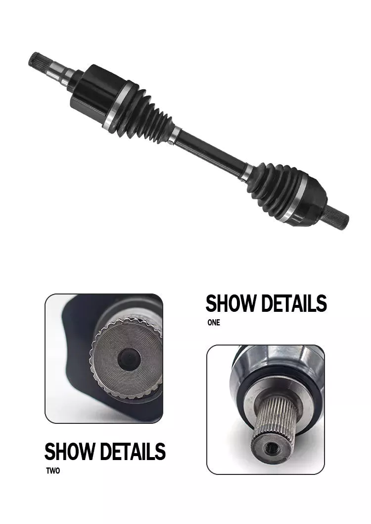
Are there any limitations or disadvantages associated with drive shafts?
While drive shafts are widely used and offer several advantages, they also have certain limitations and disadvantages that should be considered. Here’s a detailed explanation of the limitations and disadvantages associated with drive shafts:
1. Length and Misalignment Constraints:
Drive shafts have a maximum practical length due to factors such as material strength, weight considerations, and the need to maintain rigidity and minimize vibrations. Longer drive shafts can be prone to increased bending and torsional deflection, leading to reduced efficiency and potential driveline vibrations. Additionally, drive shafts require proper alignment between the driving and driven components. Misalignment can cause increased wear, vibrations, and premature failure of the drive shaft or its associated components.
2. Limited Operating Angles:
Drive shafts, especially those using U-joints, have limitations on operating angles. U-joints are typically designed to operate within specific angular ranges, and operating beyond these limits can result in reduced efficiency, increased vibrations, and accelerated wear. In applications requiring large operating angles, constant velocity (CV) joints are often used to maintain a constant speed and accommodate greater angles. However, CV joints may introduce higher complexity and cost compared to U-joints.
3. Maintenance Requirements:
Drive shafts require regular maintenance to ensure optimal performance and reliability. This includes periodic inspection, lubrication of joints, and balancing if necessary. Failure to perform routine maintenance can lead to increased wear, vibrations, and potential driveline issues. Maintenance requirements should be considered in terms of time and resources when using drive shafts in various applications.
4. Noise and Vibration:
Drive shafts can generate noise and vibrations, especially at high speeds or when operating at certain resonant frequencies. Imbalances, misalignment, worn joints, or other factors can contribute to increased noise and vibrations. These vibrations may affect the comfort of vehicle occupants, contribute to component fatigue, and require additional measures such as dampers or vibration isolation systems to mitigate their effects.
5. Weight and Space Constraints:
Drive shafts add weight to the overall system, which can be a consideration in weight-sensitive applications, such as automotive or aerospace industries. Additionally, drive shafts require physical space for installation. In compact or tightly packaged equipment or vehicles, accommodating the necessary drive shaft length and clearances can be challenging, requiring careful design and integration considerations.
6. Cost Considerations:
Drive shafts, depending on their design, materials, and manufacturing processes, can involve significant costs. Customized or specialized drive shafts tailored to specific equipment requirements may incur higher expenses. Additionally, incorporating advanced joint configurations, such as CV joints, can add complexity and cost to the drive shaft system.
7. Inherent Power Loss:
Drive shafts transmit power from the driving source to the driven components, but they also introduce some inherent power loss due to friction, bending, and other factors. This power loss can reduce overall system efficiency, particularly in long drive shafts or applications with high torque requirements. It is important to consider power loss when determining the appropriate drive shaft design and specifications.
8. Limited Torque Capacity:
While drive shafts can handle a wide range of torque loads, there are limits to their torque capacity. Exceeding the maximum torque capacity of a drive shaft can lead to premature failure, resulting in downtime and potential damage to other driveline components. It is crucial to select a drive shaft with sufficient torque capacity for the intended application.
Despite these limitations and disadvantages, drive shafts remain a widely used and effective means of power transmission in various industries. Manufacturers continuously work to address these limitations through advancements in materials, design techniques, joint configurations, and balancing processes. By carefully considering the specific application requirements and potential drawbacks, engineers and designers can mitigate the limitations and maximize the benefits of drive shafts in their respective systems.
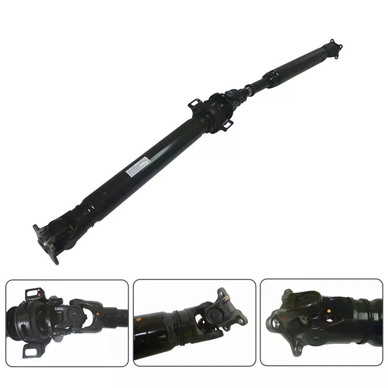
ドライブシャフトを使用している車両や機械の実例を挙げてもらえますか?
ドライブシャフトは、エンジンや動力源から車輪や駆動部品に動力を伝達するために、様々な車両や機械で広く使用されています。以下に、ドライブシャフトを使用している実際の車両や機械の例をいくつか示します。
1. 自動車:
ドライブシャフトは、特に後輪駆動または四輪駆動システムを搭載した自動車によく見られます。これらの車両では、ドライブシャフトはトランスミッションまたはトランスファーケースから、それぞれリアディファレンシャルまたはフロントディファレンシャルに動力を伝達します。これにより、エンジンの動力が車輪に分配され、車両が前進します。
2. トラックおよび商用車:
ドライブシャフトは、トラックや商用車において不可欠な部品です。トランスミッションまたはトランスファーケースから後車軸、あるいは大型トラックの場合は複数の車軸へ動力を伝達するために使用されます。商用車のドライブシャフトは、より高いトルク負荷に対応できるように設計されており、乗用車に使用されるものよりも大型で頑丈な場合が多いです。
3. 建設機械および土木機械:
掘削機、ローダー、ブルドーザー、グレーダーなど、さまざまな種類の建設機械や土木機械は、動力伝達にドライブシャフトを使用しています。これらの機械は通常、複雑な駆動系システムを備えており、ドライブシャフトを使ってエンジンから車輪や履帯に動力を伝達することで、建設現場や鉱山作業において重作業を行うことができます。
4. 農業機械:
トラクター、コンバイン、収穫機などの農業機械は、エンジンから車輪や駆動部品に動力を伝達するために駆動軸を使用します。農業機械の駆動軸は過酷な条件下にさらされることが多く、部品間の距離を可変にするために伸縮式セクションなどの追加機能が備えられている場合があります。
5. 産業機械:
製造装置、発電機、ポンプ、コンプレッサーなどの産業機械は、動力伝達システムに駆動軸を組み込んでいることが多い。これらの駆動軸は、電動モーター、エンジン、その他の動力源から様々な駆動部品に動力を伝達し、産業現場において機械が特定の作業を実行できるようにする。
6. 船舶:
船舶用途では、ドライブシャフトは一般的に、ボート、船舶、その他の水上艇において、エンジンからプロペラへ動力を伝達するために使用されます。船舶用ドライブシャフトは通常、より長く、耐腐食性や適切なシール機構など、水環境特有の課題に耐えられるように設計されています。
7. レクリエーション用車両(RV)およびモーターホーム:
キャンピングカーやモーターホームでは、駆動系の一部としてドライブシャフトがよく用いられます。これらのドライブシャフトは、トランスミッションから後輪車軸に動力を伝達し、車両の走行と推進力を生み出します。キャンピングカーのドライブシャフトには、走行中の快適性を高めるために、ダンパーや振動低減部品などの追加機能が備わっている場合もあります。
8. オフロード車およびレーシングカー:
SUV、トラック、全地形対応車(ATV)などのオフロード車やレーシングカーでは、ドライブシャフトが頻繁に使用されます。これらのドライブシャフトは、オフロード走行や高性能レースの過酷な条件に耐えられるように設計されており、効率的に動力を車輪に伝達し、最適なトラクションとパフォーマンスを確保します。
9. 鉄道車両:
鉄道システムでは、機関車や一部の車両に駆動軸が用いられます。駆動軸は機関車のエンジンから車輪または推進システムに動力を伝達し、列車が線路に沿って走行できるようにします。鉄道用の駆動軸は通常、非常に長く、一部の列車の構成における関節式または柔軟な構造に対応するための追加機能が備わっている場合があります。
10. 風力タービン:
発電に用いられる大型風力タービンは、動力伝達システムに駆動軸を組み込んでいる。駆動軸はタービンのブレードから発電機へ回転エネルギーを伝達し、発電機で電気エネルギーに変換される。風力タービンの駆動軸は、風によって発生する大きなトルクと回転力に耐えられるよう設計されている。
これらの例は、効率的な動力伝達と推進のために駆動軸に依存する車両や機械の幅広い範囲を示しています。駆動軸は様々な産業において不可欠な部品であり、動力源から駆動される部品への動力伝達を可能にし、最終的には移動、操作、または特定の作業の遂行を容易にします。
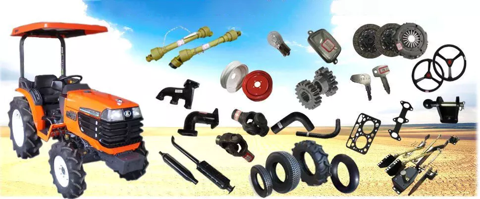
Are there variations in drive shaft designs for different types of machinery?
Yes, there are variations in drive shaft designs to cater to the specific requirements of different types of machinery. The design of a drive shaft is influenced by factors such as the application, power transmission needs, space limitations, operating conditions, and the type of driven components. Here’s an explanation of how drive shaft designs can vary for different types of machinery:
1. Automotive Applications:
In the automotive industry, drive shaft designs can vary depending on the vehicle’s configuration. Rear-wheel-drive vehicles typically use a single-piece or two-piece drive shaft, which connects the transmission or transfer case to the rear differential. Front-wheel-drive vehicles often use a different design, employing a drive shaft that combines with the constant velocity (CV) joints to transmit power to the front wheels. All-wheel-drive vehicles may have multiple drive shafts to distribute power to all wheels. The length, diameter, material, and joint types can differ based on the vehicle’s layout and torque requirements.
2. Industrial Machinery:
Drive shaft designs for industrial machinery depend on the specific application and power transmission requirements. In manufacturing machinery, such as conveyors, presses, and rotating equipment, drive shafts are designed to transfer power efficiently within the machine. They may incorporate flexible joints or use a splined or keyed connection to accommodate misalignment or allow for easy disassembly. The dimensions, materials, and reinforcement of the drive shaft are selected based on the torque, speed, and operating conditions of the machinery.
3. Agriculture and Farming:
Agricultural machinery, such as tractors, combines, and harvesters, often requires drive shafts that can handle high torque loads and varying operating angles. These drive shafts are designed to transmit power from the engine to attachments and implements, such as mowers, balers, tillers, and harvesters. They may incorporate telescopic sections to accommodate adjustable lengths, flexible joints to compensate for misalignment during operation, and protective shielding to prevent entanglement with crops or debris.
4. Construction and Heavy Equipment:
Construction and heavy equipment, including excavators, loaders, bulldozers, and cranes, require robust drive shaft designs capable of transmitting power in demanding conditions. These drive shafts often have larger diameters and thicker walls to handle high torque loads. They may incorporate universal joints or CV joints to accommodate operating angles and absorb shocks and vibrations. Drive shafts in this category may also have additional reinforcements to withstand the harsh environments and heavy-duty applications associated with construction and excavation.
5. Marine and Maritime Applications:
Drive shaft designs for marine applications are specifically engineered to withstand the corrosive effects of seawater and the high torque loads encountered in marine propulsion systems. Marine drive shafts are typically made from stainless steel or other corrosion-resistant materials. They may incorporate flexible couplings or dampening devices to reduce vibration and mitigate the effects of misalignment. The design of marine drive shafts also considers factors such as shaft length, diameter, and support bearings to ensure reliable power transmission in marine vessels.
6. Mining and Extraction Equipment:
In the mining industry, drive shafts are used in heavy machinery and equipment such as mining trucks, excavators, and drilling rigs. These drive shafts need to withstand extremely high torque loads and harsh operating conditions. Drive shaft designs for mining applications often feature larger diameters, thicker walls, and specialized materials such as alloy steel or composite materials. They may incorporate universal joints or CV joints to handle operating angles, and they are designed to be resistant to abrasion and wear.
These examples highlight the variations in drive shaft designs for different types of machinery. The design considerations take into account factors such as power requirements, operating conditions, space constraints, alignment needs, and the specific demands of the machinery or industry. By tailoring the drive shaft design to the unique requirements of each application, optimal power transmission efficiency and reliability can be achieved.


editor by CX 2024-03-29

























