
产品描述
产品描述
A large helical gear shaft is a mechanical component consisting of a large cylindrical shaft with helical gears mounted on it. These gears have teeth that are arranged at an angle to the axis of the shaft, enabling smooth and efficient power transmission in various industrial machines and equipment.
Large helical gear shafts are commonly used in applications such as heavy machinery, automotive transmissions, and industrial equipment to transmit rotational motion and torque.
|
|
|||||||||||||||||||||||||||||||||||
★★★High Load Capacity: Large helical gear shafts are designed to handle significant loads and transmit high levels of torque. The helical gear design allows for a greater tooth engagement, resulting in improved load distribution and higher load-carrying capacity compared to other gear types.
★★★Smooth and Quiet Operation: Helical gears have a gradual engagement of teeth, which reduces noise and vibration during operation. The helix angle of the teeth helps to distribute the load smoothly, minimizing impact and ensuring a quieter gear system.
★★★Increased Efficiency: The helical gear design provides a larger contact area between the teeth, resulting in higher efficiency compared to other gear types. This leads to reduced power losses and improved overall system efficiency.
★★★Greater Tooth Strength: The helical gear teeth are longer and have a larger surface area compared to spur gears, providing increased tooth strength. This makes large helical gear shafts more resistant to wear and fatigue, allowing them to withstand heavy loads and prolonged use.
★★★Improved Gear Meshing: Helical gears offer a gradual engagement of teeth, which results in a smoother meshing action. This helps to minimize backlash, improve gear accuracy, and reduce the likelihood of tooth damage during gear engagement.
★★★多功能性: Large helical gear shafts can be used in a wide range of applications, including industrial machinery, heavy equipment, marine propulsion systems, and power transmission systems. Their versatility makes them suitable for various industries and sectors.
★★★Reliability and Durability: The use of high-quality materials, precise manufacturing techniques, and rigorous quality control ensures that large helical gear shafts are reliable and durable. They are designed to withstand heavy loads, extreme operating conditions, and long service life.
公司简介
/* 2571 年 1 月 22 日 19:08:37 */!function(){function s(e,r){var a,o={};try{e&&e.split(“,”).forEach(function(e,t){e&&(a=e.match(/(.*?):(.*)$/))&&1
| 材料: | 合金钢 |
|---|---|
| 加载: | 传动轴 |
| 刚度和柔韧性: | 刚度/刚性轴 |
| 定制化: |
可用的
| 定制请求 |
|---|
.shipping-cost-tm .tm-status-off{background: none;padding:0;color: #1470cc}
| 运费:
每件商品预计运费。 |
关于运费和预计送达时间。 |
|---|
| 付款方式: |
|
|---|---|
|
首付款 全额付款 |
| 货币: | US$ |
|---|
| 退货和退款: | 您可以在收到产品后 30 天内申请退款。 |
|---|
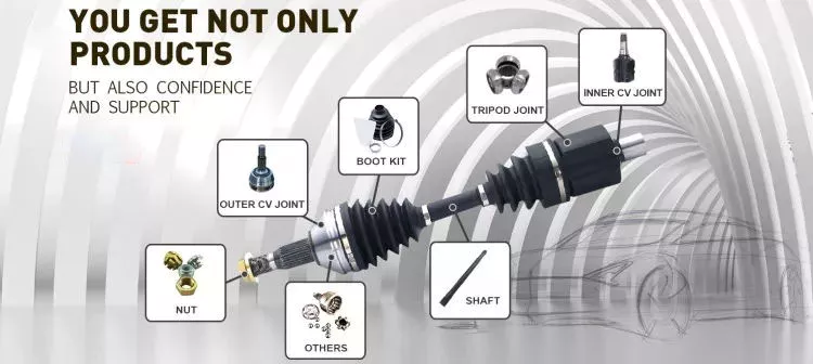
How do drive shafts ensure efficient power transfer while maintaining balance?
Drive shafts employ various mechanisms to ensure efficient power transfer while maintaining balance. Efficient power transfer refers to the ability of the drive shaft to transmit rotational power from the source (such as an engine) to the driven components (such as wheels or machinery) with minimal energy loss. Balancing, on the other hand, involves minimizing vibrations and eliminating any uneven distribution of mass that can cause disturbances during operation. Here’s an explanation of how drive shafts achieve both efficient power transfer and balance:
1. Material Selection:
The material selection for drive shafts is crucial for maintaining balance and ensuring efficient power transfer. Drive shafts are commonly made from materials such as steel or aluminum alloys, chosen for their strength, stiffness, and durability. These materials have excellent dimensional stability and can withstand the torque loads encountered during operation. By using high-quality materials, drive shafts can minimize deformation, flexing, and imbalances that could compromise power transmission and generate vibrations.
2. 设计考虑因素:
The design of the drive shaft plays a significant role in both power transfer efficiency and balance. Drive shafts are engineered to have appropriate dimensions, including diameter and wall thickness, to handle the anticipated torque loads without excessive deflection or vibration. The design also considers factors such as the length of the drive shaft, the number and type of joints (such as universal joints or constant velocity joints), and the use of balancing weights. By carefully designing the drive shaft, manufacturers can achieve optimal power transfer efficiency while minimizing the potential for imbalance-induced vibrations.
3. Balancing Techniques:
Balance is crucial for drive shafts as any imbalance can cause vibrations, noise, and accelerated wear. To maintain balance, drive shafts undergo various balancing techniques during the manufacturing process. Static and dynamic balancing methods are employed to ensure that the mass distribution along the drive shaft is uniform. Static balancing involves adding counterweights at specific locations to offset any weight imbalances. Dynamic balancing is performed by spinning the drive shaft at high speeds and measuring any vibrations. If imbalances are detected, additional adjustments are made to achieve a balanced state. These balancing techniques help minimize vibrations and ensure smooth operation of the drive shaft.
4. Universal Joints and Constant Velocity Joints:
Drive shafts often incorporate universal joints (U-joints) or constant velocity (CV) joints to accommodate misalignment and maintain balance during operation. U-joints are flexible joints that allow for angular movement between shafts. They are typically used in applications where the drive shaft operates at varying angles. CV joints, on the other hand, are designed to maintain a constant velocity of rotation and are commonly used in front-wheel-drive vehicles. By incorporating these joints, drive shafts can compensate for misalignment, reduce stress on the shaft, and minimize vibrations that can negatively impact power transfer efficiency and balance.
5. Maintenance and Inspection:
Regular maintenance and inspection of drive shafts are essential for ensuring efficient power transfer and balance. Periodic checks for wear, damage, or misalignment can help identify any issues that may affect the drive shaft’s performance. Lubrication of the joints and proper tightening of fasteners are also critical for maintaining optimal operation. By adhering to recommended maintenance procedures, any imbalances or inefficiencies can be addressed promptly, ensuring continued efficient power transfer and balance.
In summary, drive shafts ensure efficient power transfer while maintaining balance through careful material selection, thoughtful design considerations, balancing techniques, and the incorporation of flexible joints. By optimizing these factors, drive shafts can transmit rotational power smoothly and reliably, minimizing energy losses and vibrations that can impact performance and longevity.

How do drive shafts handle variations in load and vibration during operation?
Drive shafts are designed to handle variations in load and vibration during operation by employing various mechanisms and features. These mechanisms help ensure smooth power transmission, minimize vibrations, and maintain the structural integrity of the drive shaft. Here’s a detailed explanation of how drive shafts handle load and vibration variations:
1. Material Selection and Design:
Drive shafts are typically made from materials with high strength and stiffness, such as steel alloys or composite materials. The material selection and design take into account the anticipated loads and operating conditions of the application. By using appropriate materials and optimizing the design, drive shafts can withstand the expected variations in load without experiencing excessive deflection or deformation.
2. Torque Capacity:
Drive shafts are designed with a specific torque capacity that corresponds to the expected loads. The torque capacity takes into account factors such as the power output of the driving source and the torque requirements of the driven components. By selecting a drive shaft with sufficient torque capacity, variations in load can be accommodated without exceeding the drive shaft’s limits and risking failure or damage.
3. 动态平衡:
During the manufacturing process, drive shafts can undergo dynamic balancing. Imbalances in the drive shaft can result in vibrations during operation. Through the balancing process, weights are strategically added or removed to ensure that the drive shaft spins evenly and minimizes vibrations. Dynamic balancing helps to mitigate the effects of load variations and reduces the potential for excessive vibrations in the drive shaft.
4. Dampers and Vibration Control:
Drive shafts can incorporate dampers or vibration control mechanisms to further minimize vibrations. These devices are typically designed to absorb or dissipate vibrations that may arise from load variations or other factors. Dampers can be in the form of torsional dampers, rubber isolators, or other vibration-absorbing elements strategically placed along the drive shaft. By managing and attenuating vibrations, drive shafts ensure smooth operation and enhance overall system performance.
5. CV Joints:
Constant Velocity (CV) joints are often used in drive shafts to accommodate variations in operating angles and to maintain a constant speed. CV joints allow the drive shaft to transmit power even when the driving and driven components are at different angles. By accommodating variations in operating angles, CV joints help minimize the impact of load variations and reduce potential vibrations that may arise from changes in the driveline geometry.
6. Lubrication and Maintenance:
Proper lubrication and regular maintenance are essential for drive shafts to handle load and vibration variations effectively. Lubrication helps reduce friction between moving parts, minimizing wear and heat generation. Regular maintenance, including inspection and lubrication of joints, ensures that the drive shaft remains in optimal condition, reducing the risk of failure or performance degradation due to load variations.
7. Structural Rigidity:
Drive shafts are designed to have sufficient structural rigidity to resist bending and torsional forces. This rigidity helps maintain the integrity of the drive shaft when subjected to load variations. By minimizing deflection and maintaining structural integrity, the drive shaft can effectively transmit power and handle variations in load without compromising performance or introducing excessive vibrations.
8. Control Systems and Feedback:
In some applications, drive shafts may be equipped with control systems that actively monitor and adjust parameters such as torque, speed, and vibration. These control systems use sensors and feedback mechanisms to detect variations in load or vibrations and make real-time adjustments to optimize performance. By actively managing load variations and vibrations, drive shafts can adapt to changing operating conditions and maintain smooth operation.
In summary, drive shafts handle variations in load and vibration during operation through careful material selection and design, torque capacity considerations, dynamic balancing, integration of dampers and vibration control mechanisms, utilization of CV joints, proper lubrication and maintenance, structural rigidity, and, in some cases, control systems and feedback mechanisms. By incorporating these features and mechanisms, drive shafts ensure reliable and efficient power transmission while minimizing the impact of load variations and vibrations on overall system performance.
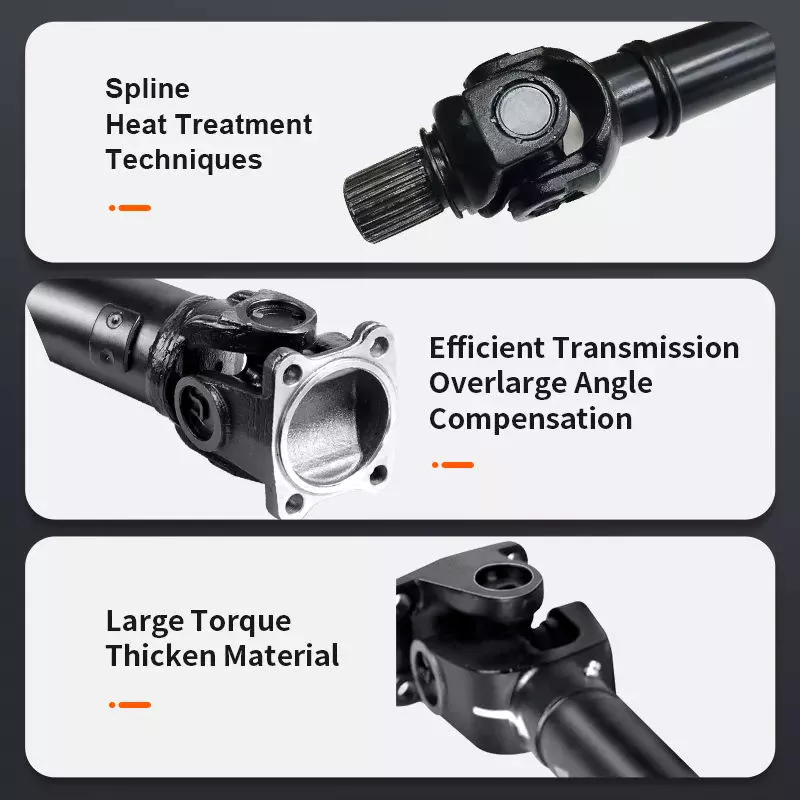
传动轴在各种应用中如何传递旋转动力?
在各种应用中,传动轴在将发动机或动力源的旋转动力传递到车轮或被驱动部件方面起着至关重要的作用。无论是在车辆还是机械中,传动轴都能实现高效的动力传输,并促进不同系统的运行。以下详细解释了传动轴如何传递旋转动力:
1. 车辆应用:
在车辆中,传动轴负责将发动机的旋转动力传递到车轮,使车辆能够行驶。传动轴连接变速箱或传动装置的输出轴和差速器,差速器再将动力分配到车轮。发动机产生扭矩后,扭矩通过传动轴传递到车轮,推动车辆前进。这种动力传递使车辆能够加速、保持速度并克服阻力,例如摩擦力和坡度。
2. 机械应用:
在机械设备中,传动轴用于将发动机或电动机的旋转动力传递到各种驱动部件。例如,在工业机械中,传动轴可用于将动力传递给泵、发电机、传送带或其他机械系统。在农业机械中,传动轴通常用于连接动力源和收割机、打捆机或灌溉系统等设备。传动轴通过将旋转动力传递给必要的部件,使这些机器能够执行其预期功能。
3. 动力传输:
传动轴旨在高效可靠地传递旋转动力。它们能够将发动机产生的强大扭矩传递至车轮或被驱动部件。发动机产生的扭矩通过传动轴传递,几乎没有动力损失。通过保持发动机与被驱动部件之间的刚性连接,传动轴确保发动机产生的动力能够有效地用于完成有用的工作。
4. 柔性联轴器:
传动轴的关键功能之一是提供发动机/变速器与车轮或被驱动部件之间的柔性连接。这种柔性使传动轴能够适应角度运动,并补偿发动机与被驱动系统之间的不对中。在车辆中,当悬架系统运动或车轮遇到不平坦的路面时,传动轴会调整其长度和角度,以保持恒定的动力传输。这种柔性有助于防止传动系统部件承受过大的压力,并确保动力传输的平稳性。
5. 扭矩和速度传递:
传动轴负责传递扭矩和转速。扭矩是指发动机或动力源产生的旋转力,而转速是指每分钟的转数(RPM)。传动轴必须能够承受应用所需的扭矩,且不会过度扭曲或弯曲。此外,它们还需要保持所需的转速,以确保被驱动部件的正常运转。传动轴的合理设计、材料选择和平衡有助于实现高效的扭矩和转速传递。
6. 长度和平衡:
传动轴的长度和平衡是影响其性能的关键因素。传动轴的长度取决于发动机或动力源与被驱动部件之间的距离。其尺寸应适当,以避免过度振动或弯曲。传动轴经过精心平衡,以最大限度地减少振动和旋转不平衡,这些因素会影响传动系统的整体性能、舒适性和使用寿命。
7. 安全和维护:
传动轴需要采取适当的安全措施并定期维护。在车辆中,传动轴通常被包裹在保护管或壳体内,以防止与运动部件接触,从而降低受伤风险。在机械设备中,裸露的传动轴周围也可能安装安全护罩或防护装置,以保护操作人员免受潜在危险。定期维护包括检查传动轴的磨损、损坏或错位情况,并确保万向节得到充分润滑。这些措施有助于预防故障,确保最佳性能,并延长传动轴的使用寿命。
总而言之,传动轴在各种应用中传递旋转动力方面发挥着至关重要的作用。无论是在车辆还是机械中,传动轴都能实现从发动机或动力源到车轮或被驱动部件的高效动力传输。它们提供柔性联轴器,处理扭矩和速度传递,适应角度运动,并有助于系统的安全性和维护。通过有效地传递旋转动力,传动轴促进了众多行业中车辆和机械的运行和性能。


editor by CX 2024-04-17

























