
Descrição do produto
Descrição do produto
Garantia
1 Year
Applicable Industries
Hotels, Garment Shops, Building Material Shops, Manufacturing Plant, Machinery Repair Shops, Food & Beverage Factory, Farms, Restaurant, Home Use, Retail, Food Shop, Printing Shops, Construction works , Energy & Mining, Food & Beverage Shops, Other, Advertising Company
Weight (KG)
1
Showroom Location
Viet Nam
Video outgoing-inspection
Provided
Machinery Test Report
Provided
Marketing Type
Ordinary Product
Warranty of core components
1 Year
Core Components
PLC, Engine, Bearing, Gearbox, Motor, Pressure vessel, Gear, Pump
Material
steel
Place of CHINAMFG
ZheJiang , China
Condition
New
Structure
Haste
Coatings
Personalizado
Torque Capacity
Personalizado
Número do modelo
Personalizado
Nome da marca
NON
Description
Haste
Machining equipment
CNC mill,lathe and grind machine
Material
stainless steel, aluminium, carbon
Surface
Grinding and polishing
Shape
Personalizado
Sampling time
10days
Production time
20days
Embalagem
Protective packing
Tolerance
±0.001
OEM
Welcome
Production Process
Company Profile
HangZhou HUANENGDA SPRING CO.,LTD
HangZhou HuaNengDa Spring Co., Ltd. is located in Tong ‘an District, HangZhou City, ZheJiang Province, China. It is a hardware factory specializing in R&D design, manufacture and sales of precision components. The company introduces domestic and foreign advanced equipment and production technology, adopts CNC high-precision computer machine, compression spring machine, CNC five-axis linkage machining center, CNC turning and milling compound, 300 tons of punch and other mechanical equipment,and employs senior engineers with more than 10 years of work experience to debug mechanical equipment and customize production.
With the business philosophy of honesty, pragmatism and excellence, HuaNengDa Spring Company is dedicated to serving customers at home and abroad. We hope that the products of HuaNengDa will help your business to be more brilliant, let us build a bright future in the high-tech era!
The testimony is pragmatic and the attitude of the people. Quality service is the pursuit of the people!
Factory Workshop
Production Procedur
Quality Inspection
Packing And Shipping
Our Service
Perguntas frequentes
1.Small order quantity is workable
From the initial sample design of the spring to the mass production of the springs, we can quickly reach your manufacturing goals and immediately provide the best products because we have an excellent production management system and expertly trained technical personnel.
2.Committed to high quality production
To keep HuaNengDa Springs at the forefront of the industry, we have implemented a stringent internal quality control system and regularly import the latest manufacturing equipment and instruments. Through our precise manufacturing technology and expert mold making process, we provide our customers with the best products and service.
3.Efficiency in manufacturing
Our company’s machinery and equipment are controlled by CNC computers. In order to respond to international needs and standards, we continuously update and upgrade our equipment every year. Our machines effectively increase production capacity and save on manufacturing costs. The manufacturing department is the most important core of the whole company and by treating it with utmost importance, we reap great benefits in manufacturing efficiency.
4.Excellent customization services
HuaNengDa’s R&D team designs and completes customized products according to the needs of customers. From the selection of materials to the function of the products, we can design and develop products to suite different customers’ requirements. We are constantly involving ourselves in all aspects of the industry because only by having a complete view and analysis of the industry, can there be innovative breakthroughs.
Payment term
*T/T : 30% pre T/T, 70% before delivery.
*Trade Assurance
Service
*Delivery on time.
*Shipped by a convenient and cost-effective way.
*Good after-selling, 24 hours service for you.
Embalagem
*A: Poly bag, Plstic tray ,small box, carton.
*B: According to customers’ requirements.
Delivery
*Sample: 7-10 days after deposit received.
*Batch goods: 12-15 days after samples approved. /* January 22, 2571 19:08:37 */!function(){function s(e,r){var a,o={};try{e&&e.split(“,”).forEach(function(e,t){e&&(a=e.match(/(.*?):(.*)$/))&&1
| Condition: | New |
|---|---|
| Certification: | ISO9001 |
| Standard: | DIN, ASTM, GOST, GB, JIS, ANSI, BS |
| Customized: | Personalizado |
| Material: | Steel,Stainless Steel,Iron |
| Aplicativo: | Metal Processing Machinery Parts |
| Exemplos: |
US$ 10/Piece
1 unidade (pedido mínimo) | |
|---|
| Personalização: |
Disponível
| Solicitação personalizada |
|---|

How do PTO shafts handle variations in length and connection methods?
PTO (Power Take-Off) shafts are designed to handle variations in length and connection methods to accommodate different equipment setups and ensure efficient power transfer. PTO shafts need to be adjustable in length to bridge the distance between the power source and the driven machinery. Additionally, they must provide versatile connection methods to connect to a wide range of equipment. Here’s a detailed explanation of how PTO shafts handle variations in length and connection methods:
1. Design telescópico: PTO shafts often feature a telescoping design, allowing them to be adjusted in length to suit different equipment configurations. The telescoping feature enables the shaft to extend or retract, accommodating varying distances between the power source (such as a tractor or engine) and the driven machinery. By adjusting the length of the PTO shaft, it can be properly aligned and connected to ensure optimal power transfer. Telescoping PTO shafts typically consist of multiple tubular sections that slide into one another, providing flexibility in length adjustment.
2. Splined Shafts: PTO shafts commonly employ splined shafts as the primary connection method between the power source and driven machinery. Splines are a series of ridges or grooves along the shaft that interlock with corresponding grooves in the mating component. The splined connection allows for torque transfer while maintaining alignment between the power source and driven machinery. Splined shafts can handle variations in length by extending or retracting the telescoping sections while still maintaining a solid connection between the power source and the driven equipment.
3. Adjustable Sliding Yokes: PTO shafts typically feature adjustable sliding yokes on one or both ends of the shaft. These yokes allow for angular adjustment, accommodating variations in the alignment between the power source and driven machinery. The sliding yokes can be moved along the splined shaft to achieve the desired angle and maintain proper alignment. This flexibility ensures that the PTO shaft can handle length variations while ensuring efficient power transfer without placing excessive strain on the universal joints or other components.
4. Universal Joints: Universal joints are integral components of PTO shafts that allow for angular misalignment between the power source and driven machinery. They consist of a cross-shaped yoke with bearings that transmit torque between connected shafts while accommodating misalignment. Universal joints provide flexibility in connecting PTO shafts to equipment that may not be perfectly aligned. As the PTO shaft length varies, the universal joints compensate for the changes in angle, allowing for smooth power transmission even when there are variations in length or misalignment between the power source and driven machinery.
5. Coupling Mechanisms: PTO shafts utilize various coupling mechanisms to securely connect to the power source and driven machinery. These mechanisms often involve a combination of splines, bolts, locking pins, or quick-release mechanisms. The coupling methods can vary depending on the specific equipment and industry requirements. The versatility of PTO shafts allows for the use of different coupling methods, ensuring a reliable and secure connection regardless of the length variation or equipment configuration.
6. Customization Options: PTO shafts can be customized to handle specific length variations and connection methods. Manufacturers offer options to select different lengths of telescoping sections to match the specific distance between the power source and driven machinery. Additionally, PTO shafts can be tailored to accommodate various connection methods through the selection of splined shaft sizes, yoke designs, and coupling mechanisms. This customization enables PTO shafts to meet the specific requirements of different equipment setups, ensuring optimal power transfer and compatibility.
7. Safety Considerations: When handling variations in length and connection methods, it is essential to consider safety. PTO shafts incorporate protective guards and shields to prevent accidental contact with rotating components. These safety measures must be appropriately adjusted and installed to provide adequate coverage and protection, regardless of the PTO shaft’s length or connection configuration. Safety guidelines and regulations should be followed to ensure the proper installation, adjustment, and use of PTO shafts in order to prevent accidents or injuries.
By incorporating telescoping designs, splined shafts, adjustable sliding yokes, universal joints, and versatile coupling mechanisms, PTO shafts can handle variations in length and connection methods. The flexibility of PTO shafts allows them to adapt to different equipment setups, ensuring efficient power transfer while maintaining alignment and safety.

How do PTO shafts handle variations in load and torque during operation?
PTO (Power Take-Off) shafts are designed to handle variations in load and torque during operation by employing specific mechanisms and features that ensure efficient power transfer and protection against overload conditions. Here’s a detailed explanation of how PTO shafts handle variations in load and torque:
1. Mechanical Design: PTO shafts are engineered with robust mechanical design principles that enable them to handle variations in load and torque. They are typically constructed using high-strength materials such as steel, which provides durability and resistance to bending or twisting forces. The shaft’s diameter, wall thickness, and overall dimensions are carefully calculated to withstand the expected torque levels and load variations. The mechanical design of the PTO shaft ensures that it can transmit power reliably and accommodate the dynamic forces encountered during operation.
2. Universal Joints: Universal joints are a key component of PTO shafts that allow for flexibility and compensation of misalignment between the power source and driven machinery. These joints can accommodate variations in angular alignment, which may occur due to changes in load or movement of the machinery. Universal joints consist of a cross-shaped yoke with needle bearings that allow for smooth rotation and transfer of torque, even when the shafts are not perfectly aligned. The design of universal joints enables PTO shafts to handle variations in load and torque while maintaining consistent power transmission.
3. Embreagens deslizantes: Slip clutches are often incorporated into PTO shafts to provide overload protection. These clutches allow the PTO shaft to slip or disengage momentarily when excessive torque or resistance is encountered. Slip clutches typically consist of friction plates that can be adjusted to a specific torque setting. When the torque surpasses the predetermined limit, the clutch slips, preventing damage to the PTO shaft and connected equipment. Slip clutches are particularly useful when sudden changes in load or torque occur, providing a safety mechanism to protect the PTO shaft and associated machinery.
4. Torque Limiters: Torque limiters are another protective feature found in some PTO shafts. These devices are designed to automatically disengage the power transmission when a predetermined torque threshold is exceeded. Torque limiters can be mechanical, such as shear pin couplings or friction clutches, or electronic, utilizing sensors and control systems. When the torque exceeds the set limit, the torque limiter disengages, preventing further power transfer and protecting the PTO shaft from overload conditions. Torque limiters are effective in handling sudden spikes in torque and safeguarding the PTO shaft and associated equipment.
5. Maintenance and Inspection: Regular maintenance and inspection of PTO shafts are essential to ensure their proper functioning and ability to handle variations in load and torque. Routine maintenance includes lubrication of universal joints, inspection of shaft integrity, and tightening of fasteners. Regular inspections allow for early detection of wear, misalignment, or other issues that may affect the PTO shaft’s performance. By addressing maintenance and inspection requirements, operators can identify and address any concerns that may arise due to variations in load and torque, ensuring the continued safe and efficient operation of the PTO shaft.
6. Operator Awareness and Control: Operators play a crucial role in managing variations in load and torque during PTO shaft operation. They should be aware of the machinery’s operational limits, including the recommended torque ratings and load capacities of the PTO shaft. Proper training and understanding of the equipment’s capabilities enable operators to make informed decisions and adjust the operation when encountering significant load or torque changes. Operators should also be vigilant in monitoring the equipment’s performance, watching for any signs of excessive vibration, noise, or other indications of potential issues related to load and torque variations.
By incorporating robust mechanical design, utilizing universal joints, slip clutches, torque limiters, and implementing proper maintenance practices, PTO shafts are equipped to handle variations in load and torque during operation. These features ensure reliable power transmission, protect against overload conditions, and contribute to the safe and efficient functioning of the PTO shaft and the machinery it drives.
Você pode explicar os diferentes tipos de eixos de tomada de força (PTO) e suas aplicações?
Os eixos de tomada de força (PTO, na sigla em inglês) vêm em vários tipos, cada um projetado para aplicações e requisitos específicos. Os diferentes tipos de eixos de tomada de força oferecem versatilidade e compatibilidade com uma ampla gama de máquinas e implementos. Aqui está uma explicação dos tipos mais comuns de eixos de tomada de força e suas aplicações:
1. Eixo da tomada de força padrão: O eixo de tomada de força (TDF) padrão, também conhecido como eixo estriado, é o tipo mais comum usado em máquinas agrícolas e industriais. Consiste em um eixo de aço maciço com estrias ou ranhuras ao longo de seu comprimento. O eixo de TDF padrão normalmente possui seis estrias, embora também existam variações com quatro ou oito estrias. Este tipo de eixo de TDF é amplamente utilizado em tratores e diversos implementos, incluindo segadoras, enfardadeiras, cultivadores e roçadeiras. As estrias proporcionam uma conexão segura entre a fonte de energia e a máquina acionada, garantindo uma transferência de potência eficiente.
2. Parafuso de cisalhamento do eixo da tomada de força: Os eixos de tomada de força (TDF) com parafuso de cisalhamento são projetados com um recurso de segurança que permite a separação do eixo em caso de sobrecarga ou choque repentino, protegendo os componentes da transmissão. Esses eixos de TDF incorporam um mecanismo de parafuso de cisalhamento que conecta a tomada de força do trator à máquina acionada. Em caso de carga excessiva ou resistência repentina, o parafuso de cisalhamento é projetado para romper, desconectando o eixo de TDF e evitando danos à transmissão. Os eixos de TDF com parafuso de cisalhamento são comumente usados em equipamentos que podem encontrar obstruções repentinas ou situações de alta tensão, como trituradores de madeira, destocadores e cortadores rotativos de alta potência.
3. Eixo da tomada de força com embreagem de fricção: Os eixos de tomada de força (TDF) com embreagem de fricção possuem um mecanismo de embreagem que permite o engate e desengate suaves da transmissão de potência. Esses eixos de TDF geralmente incorporam um disco de fricção e uma placa de pressão, semelhante a um sistema de embreagem tradicional de veículo. A embreagem de fricção permite que os operadores engatem ou desengatem a transmissão de potência gradualmente, reduzindo impactos e minimizando o desgaste dos componentes da transmissão. Os eixos de TDF com embreagem de fricção são comumente usados em aplicações onde é necessário um controle preciso do engate de potência, como em bombas hidráulicas, geradores e misturadores industriais.
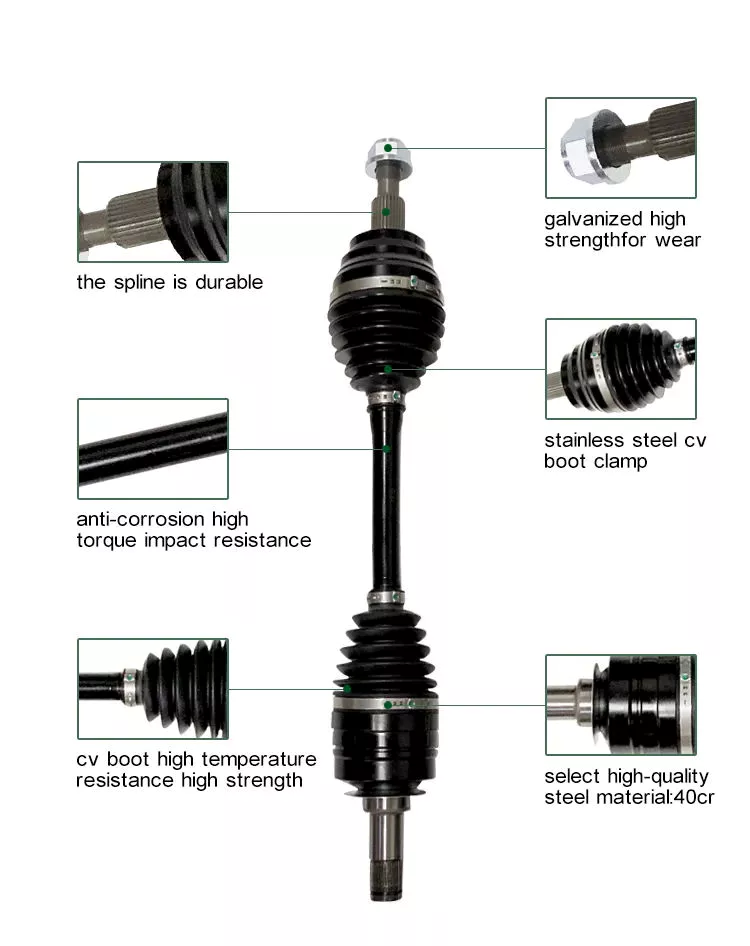
4. Eixo da tomada de força (TDF) de velocidade constante (CV): Eixos de tomada de força (TDF) de velocidade constante (CV), também conhecidos como eixos homocinéticos, são projetados para acomodar altos ângulos de desalinhamento sem afetar a transmissão de potência. Eles utilizam um mecanismo de junta universal que permite uma transferência de potência suave mesmo quando a máquina acionada está em um ângulo em relação à fonte de energia. Os eixos de TDF CV são frequentemente usados em aplicações onde a máquina requer uma amplitude significativa de movimento ou articulação, como em carregadeiras articuladas, manipuladores telescópicos e pulverizadores autopropelidos.
5. Eixo telescópico da tomada de força: Eixos telescópicos de tomada de força (TDF) têm comprimento ajustável, permitindo flexibilidade na configuração do equipamento e em diferentes distâncias entre a fonte de energia e a máquina acionada. Consistem em dois ou mais eixos concêntricos que deslizam um dentro do outro, possibilitando a extensão ou retração do eixo da TDF conforme a necessidade. Eixos telescópicos de TDF são comumente utilizados em aplicações onde a distância entre a tomada de força do trator e o implemento varia, como em implementos frontais, sopradores de neve e vagões autocarregáveis. O design telescópico facilita a adaptação a diferentes configurações de equipamentos e minimiza o risco de o eixo da TDF arrastar no solo.
6. Eixo da tomada de força da caixa de engrenagens: Os eixos de tomada de força (TDF) com caixa de engrenagens são projetados para adaptar a transmissão de potência entre diferentes velocidades ou direções de rotação. Eles incorporam um mecanismo de caixa de engrenagens que permite a redução ou o aumento da velocidade, bem como a capacidade de alterar o sentido de rotação. Os eixos de TDF com caixa de engrenagens são comumente usados em aplicações onde a máquina acionada requer uma velocidade ou sentido de rotação diferente daquele da tomada de força do trator. Exemplos incluem transportadores de grãos, misturadores de ração e equipamentos industriais que requerem relações de velocidade específicas ou capacidade de reversão.
É importante observar que a disponibilidade e as aplicações específicas dos tipos de eixos de tomada de força (TDF) podem variar de acordo com fatores regionais e específicos do setor. Além disso, determinadas máquinas ou implementos podem exigir eixos de TDF especializados ou personalizados para atender a requisitos específicos.
Em resumo, os diferentes tipos de eixos de tomada de força (TDF), como os eixos padrão, de parafuso de cisalhamento, de embreagem de fricção, de velocidade constante (CV), telescópicos e de caixa de engrenagens, oferecem versatilidade e compatibilidade com diversas máquinas e implementos. Cada tipo de eixo de TDF é projetado para atender a necessidades específicas, como eficiência na transferência de potência, segurança, engate suave, tolerância a desalinhamento, adaptabilidade e ajuste de velocidade/direção. Compreender os diferentes tipos de eixos de TDF e suas aplicações é crucial para selecionar o eixo apropriado para a máquina em questão e garantir desempenho e confiabilidade ideais.

editor by CX 2024-04-22

























