
Productbeschrijving
Productbeschrijving
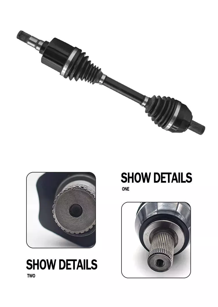
| product name | gearbox drive shaft |
| Product number | 2201-0571 |
| Specification | standard |
| Materiaal | Metal |
| performance | hight |
| Application classification | drive shaft |
| Applicable models | Yutong/zhongtong/haige bus |
| Origin | China |
| Package | Carton |
| Transportation method | According to customer requirements |
Detailed Photos
Product material number
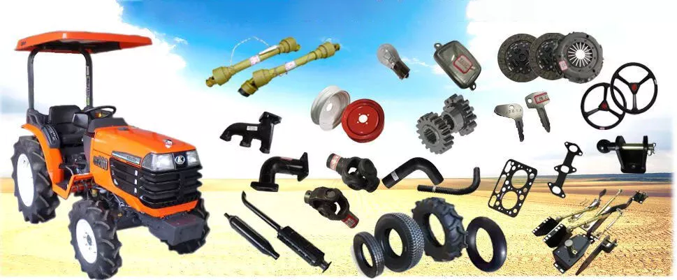
Our company operates a full range of accessories for buses and trucks of multiple brands. If the product you need is not on my list, please send me an email and I will send you the exact information and price based on your description or item number.
| 2201-05711 | 2201-01587 | 2201-0571 | 2201-01405 | 2201-00948 | 2201-5713 |
| 2201-01818 | 2201-0 0571 | 2201-57169 | 2201-02620 | 2201-00145 | 2201-03263 |
| 2201-5713 | 2201-00495 | 2201-00179 | 2201-57198 | 2201-01391 | 2201-00696 |
| 2201-00687 | 2201-01863 | 2201-05710 | 2201-00696 | 2201-01707 | 2201-01700 |
| 2201-0571 | 2201-00012 | 2201-00038 | 2201-00082 | 2201-00082A | 2201-00087 |
| 2201-00089A | 2201-00099 | 2201-5711 | 2201-5718 | 2201-5719 | 2201-00127 |
| 2201-00129 | 2201-00166A | 2201-00171 | 2201-00175 | 2201-00181 | 2201-5713 |
| 2201-05712 | 2201-05711 | 2201-05711A | 2201-05712 | 2201-05710 | 2201-05711 |
| 2201-5716 | 2201-5712 | 2201-5718 | 2201-0571 | 2201-0571 | 2201-0571 |
| 2201-0 0571 | 2201-00388 | 2201-00390 | 2201-00390A | 2201-00406 | 2201-0571 |
| 2201-00428 | 2201-00441 | 2201-00447 | 2201-00495 | 2201-0571 | 2201-0571 |
| 2201-00544 | 2201-0 0571 | 2201-00581 | 2201-00587 | 2201-00588 | 2201-00589 |
| 2201-00590 | 2201-00602 | 2201-0 0571 | 2201-00652 | 2201-00654 | 2201-00655 |
| 2201-00658 | 2201-00664 | 2201-00667 | 2201-00686 | 2201-00687 | 2201-00696 |
| 2201-00729 | 2201-0571 | 2201-0 0571 | 2201-0571 | 2201-571 | 2201-00801 |
| 2201-00808 | 2201-0571 | 2201-0 0571 | 2201-0 0571 | 2201-0 0571 | 2201-00881 |
| 2201-00948 | 2201-571 | 2201-0 0571 | 2201-57126 | 2201-57138 | 2201-57143 |
| 2201-57152 | 2201-57178 | 2201-57184 | 2201-57187 | 2201-01128 | 2201-01215 |
| 2201-01284 | 2201-01297 | 2201-01328 | 2201-01341 | 2201-01342 | 2201-01345 |
| 2201-01402 | 2201-01404 | 2201-01405 | 2201-01455 | 2201-01459 | 2201-01460 |
| 2201-01462 | 2201-01545 | 2201-01555 | 2201-01557 | 2201-01586 | 2201-01587 |
| 2201-01588 | 2201-01589 | 2201-01593 | 2201-01620 | 2201-01623 | 2201-01624 |
| 2201-01633 | 2201-01634 | 2201-01642 | 2201-01693 | 2201-01702 | 2201-01709 |
| 2201-01720 | 2201-01726 | 2201-01755 | 2201-01759 | 2201-01762 | 2201-01818 |
| 2201-01827 | 2201-01844 | 2201-01847 | 2201-01849 | 2201-01857 | 2201-01860 |
| 2201-01863 | 2201-01864 | 2201-01981 | 2201-01991 | 2201-57177 | 2201-57178 |
| 2201-57120 | 2201-57155 | 2201-57133 | 2201-57140 | 2201-57154 | 2201-57159 |
| 2201-57161 | 2201-57173 | 2201-57108 | 2201-02605 | 2201-02615 | 2201-02620 |
| 2201-02621 | 2201-02634 | 2201-57155 | 2201-57156 | 2201-57122 | 2201-57125 |
| 2201-57130 | 2201-57169 | 2201- 0571 1 | 2201-5718 | 2201-5713 | 2201-03394 |
| 2201-03453 | 5904- 0571 8 | 5904- 0571 9 | 5904-05017 | 5904-05018 | 5904-05019 |
| 5904-05062 | 5904-05063 | 5904-05064 | 5904- 0571 3 | 5904- 0571 4 | 5904- 0571 5 |
| 5912-05265 | 5912-05266 | 5913-5719 | 5913-5710 | 5913-5711 | 5913-05204 |
| 5913-05205 | 5914-57188 | 5914-57189 |
Shipping scenario
Onze voordelen
Veelgestelde vragen
Q1. How do you correctly identify the products you need?
A:Supply part number,we can check directly.
Engine and gearbox parts;if you don’t know part code,try to found engine or gear model and number.
Q2. What are your packaging conditions?
A: Generally, the goods are packed in neutral white boxes or brown cartons.
If you have a legally registered patent, the goods can be packed in your branded boxes after obtaining your authorization letter.
Q3. What are your payment terms?
A: T/T 30% as deposit, 70% before delivery. Photos of the product and packaging will be shown to you before the balance is paid.
Q4 How is your delivery time?
A: Generally, it takes 30 days after receiving the advance payment.
The specific delivery time depends on the items and quantity of the order.
Q5. Can you produce according to samples?
A: Yes, it can be developed according to your samples or technical drawings.
Q6. Do you test all goods before delivery?
A: Yes, 100% tested before delivery.
Q7: How do you make our business long-term and good relationship?
A: 1. Good quality and competitive prices ensure our customers benefit;
2.We respect every customer as our friend, we sincerely do business and make friends with them, no matter where they come from.
/* 22 januari 2571 19:08:37 */!function(){function s(e,r){var a,o={};try{e&&e.split(“,”).forEach(function(e,t){e&&(a=e.match(/(.*?):(.*)$/))&&1
| Klantenservice na aankoop: | Standard After-Sales |
|---|---|
| Voorwaarde: | Nieuw |
| Kleur: | Zwart |
| Certificering: | CE, DIN, ISO |
| Type: | C.V. Joint |
| Applicatiemerk: | Yutong |
| Voorbeelden: |
US$ 120/Piece
1 stuk (minimale bestelling) | |
|---|
Are there any limitations or disadvantages associated with drive shafts?
While drive shafts are widely used and offer several advantages, they also have certain limitations and disadvantages that should be considered. Here’s a detailed explanation of the limitations and disadvantages associated with drive shafts:
1. Length and Misalignment Constraints:
Drive shafts have a maximum practical length due to factors such as material strength, weight considerations, and the need to maintain rigidity and minimize vibrations. Longer drive shafts can be prone to increased bending and torsional deflection, leading to reduced efficiency and potential driveline vibrations. Additionally, drive shafts require proper alignment between the driving and driven components. Misalignment can cause increased wear, vibrations, and premature failure of the drive shaft or its associated components.
2. Limited Operating Angles:
Drive shafts, especially those using U-joints, have limitations on operating angles. U-joints are typically designed to operate within specific angular ranges, and operating beyond these limits can result in reduced efficiency, increased vibrations, and accelerated wear. In applications requiring large operating angles, constant velocity (CV) joints are often used to maintain a constant speed and accommodate greater angles. However, CV joints may introduce higher complexity and cost compared to U-joints.
3. Maintenance Requirements:
Drive shafts require regular maintenance to ensure optimal performance and reliability. This includes periodic inspection, lubrication of joints, and balancing if necessary. Failure to perform routine maintenance can lead to increased wear, vibrations, and potential driveline issues. Maintenance requirements should be considered in terms of time and resources when using drive shafts in various applications.
4. Noise and Vibration:
Drive shafts can generate noise and vibrations, especially at high speeds or when operating at certain resonant frequencies. Imbalances, misalignment, worn joints, or other factors can contribute to increased noise and vibrations. These vibrations may affect the comfort of vehicle occupants, contribute to component fatigue, and require additional measures such as dampers or vibration isolation systems to mitigate their effects.
5. Weight and Space Constraints:
Drive shafts add weight to the overall system, which can be a consideration in weight-sensitive applications, such as automotive or aerospace industries. Additionally, drive shafts require physical space for installation. In compact or tightly packaged equipment or vehicles, accommodating the necessary drive shaft length and clearances can be challenging, requiring careful design and integration considerations.
6. Cost Considerations:
Drive shafts, depending on their design, materials, and manufacturing processes, can involve significant costs. Customized or specialized drive shafts tailored to specific equipment requirements may incur higher expenses. Additionally, incorporating advanced joint configurations, such as CV joints, can add complexity and cost to the drive shaft system.
7. Inherent Power Loss:
Drive shafts transmit power from the driving source to the driven components, but they also introduce some inherent power loss due to friction, bending, and other factors. This power loss can reduce overall system efficiency, particularly in long drive shafts or applications with high torque requirements. It is important to consider power loss when determining the appropriate drive shaft design and specifications.
8. Limited Torque Capacity:
While drive shafts can handle a wide range of torque loads, there are limits to their torque capacity. Exceeding the maximum torque capacity of a drive shaft can lead to premature failure, resulting in downtime and potential damage to other driveline components. It is crucial to select a drive shaft with sufficient torque capacity for the intended application.
Despite these limitations and disadvantages, drive shafts remain a widely used and effective means of power transmission in various industries. Manufacturers continuously work to address these limitations through advancements in materials, design techniques, joint configurations, and balancing processes. By carefully considering the specific application requirements and potential drawbacks, engineers and designers can mitigate the limitations and maximize the benefits of drive shafts in their respective systems.

Hoe gaan aandrijfassen om met variaties in belasting en trillingen tijdens gebruik?
Aandrijfassen zijn ontworpen om variaties in belasting en trillingen tijdens gebruik op te vangen door middel van diverse mechanismen en eigenschappen. Deze mechanismen zorgen voor een soepele krachtoverbrenging, minimaliseren trillingen en behouden de structurele integriteit van de aandrijfas. Hieronder volgt een gedetailleerde uitleg over hoe aandrijfassen variaties in belasting en trillingen opvangen:
1. Materiaalkeuze en ontwerp:
Aandrijfassen worden doorgaans gemaakt van materialen met een hoge sterkte en stijfheid, zoals staallegeringen of composietmaterialen. Bij de materiaalkeuze en het ontwerp wordt rekening gehouden met de verwachte belastingen en bedrijfsomstandigheden van de toepassing. Door geschikte materialen te gebruiken en het ontwerp te optimaliseren, kunnen aandrijfassen de verwachte variaties in belasting weerstaan zonder overmatige doorbuiging of vervorming.
2. Koppelcapaciteit:
Aandrijfassen worden ontworpen met een specifiek koppelvermogen dat overeenkomt met de verwachte belastingen. Het koppelvermogen houdt rekening met factoren zoals het vermogen van de aandrijfbron en de koppelvereisten van de aangedreven componenten. Door een aandrijfas met voldoende koppelvermogen te kiezen, kunnen variaties in belasting worden opgevangen zonder de limieten van de aandrijfas te overschrijden en het risico op defecten of schade te minimaliseren.
3. Dynamische balans:
Tijdens het productieproces kunnen aandrijfassen dynamisch gebalanceerd worden. Onevenwichtigheden in de aandrijfas kunnen trillingen veroorzaken tijdens gebruik. Door middel van balanceren worden strategisch gewichten toegevoegd of verwijderd om ervoor te zorgen dat de aandrijfas gelijkmatig draait en trillingen tot een minimum worden beperkt. Dynamisch balanceren helpt de effecten van belastingvariaties te verminderen en de kans op overmatige trillingen in de aandrijfas te verkleinen.
4. Dempers en trillingsbeheersing:
Aandrijfassen kunnen dempers of trillingsbeheersingsmechanismen bevatten om trillingen verder te minimaliseren. Deze apparaten zijn doorgaans ontworpen om trillingen te absorberen of af te voeren die kunnen ontstaan door belastingvariaties of andere factoren. Dempers kunnen de vorm hebben van torsiedempers, rubberen isolatoren of andere trillingsabsorberende elementen die strategisch langs de aandrijfas zijn geplaatst. Door trillingen te beheersen en te dempen, zorgen aandrijfassen voor een soepele werking en verbeteren ze de algehele systeemprestaties.
5. Homokinetische koppelingen:
Homokinetische koppelingen (CV-koppelingen) worden vaak gebruikt in aandrijfassen om variaties in de werkingshoek op te vangen en een constante snelheid te handhaven. CV-koppelingen zorgen ervoor dat de aandrijfas kracht kan overbrengen, zelfs wanneer de aandrijvende en aangedreven componenten zich onder verschillende hoeken bevinden. Door variaties in de werkingshoek op te vangen, helpen CV-koppelingen de impact van belastingvariaties te minimaliseren en potentiële trillingen te verminderen die kunnen ontstaan door veranderingen in de geometrie van de aandrijflijn.
6. Smering en onderhoud:
Een goede smering en regelmatig onderhoud zijn essentieel voor aandrijfassen om belasting- en trillingsvariaties effectief op te vangen. Smering helpt wrijving tussen bewegende onderdelen te verminderen, waardoor slijtage en warmteontwikkeling worden geminimaliseerd. Regelmatig onderhoud, inclusief inspectie en smering van de verbindingen, zorgt ervoor dat de aandrijfas in optimale conditie blijft, waardoor het risico op storingen of prestatievermindering als gevolg van belastingvariaties wordt verkleind.
7. Structurele stijfheid:
Aandrijfassen zijn ontworpen met voldoende structurele stijfheid om buig- en torsiekrachten te weerstaan. Deze stijfheid draagt bij aan de integriteit van de aandrijfas bij wisselende belastingen. Door doorbuiging te minimaliseren en de structurele integriteit te behouden, kan de aandrijfas effectief vermogen overbrengen en wisselende belastingen opvangen zonder dat dit ten koste gaat van de prestaties of overmatige trillingen veroorzaakt.
8. Regelsystemen en terugkoppeling:
In sommige toepassingen kunnen aandrijfassen zijn uitgerust met besturingssystemen die parameters zoals koppel, snelheid en trillingen actief bewaken en aanpassen. Deze besturingssystemen gebruiken sensoren en feedbackmechanismen om variaties in belasting of trillingen te detecteren en realtime aanpassingen te maken om de prestaties te optimaliseren. Door actief om te gaan met variaties in belasting en trillingen, kunnen aandrijfassen zich aanpassen aan veranderende bedrijfsomstandigheden en een soepele werking behouden.
Samenvattend kunnen aandrijfassen variaties in belasting en trillingen tijdens bedrijf opvangen door zorgvuldige materiaalkeuze en ontwerp, overwegingen met betrekking tot het koppelvermogen, dynamische balancering, integratie van dempers en trillingsbeheersingsmechanismen, gebruik van homokinetische koppelingen, juiste smering en onderhoud, structurele stijfheid en, in sommige gevallen, besturingssystemen en feedbackmechanismen. Door deze kenmerken en mechanismen te integreren, zorgen aandrijfassen voor een betrouwbare en efficiënte krachtoverbrenging en minimaliseren ze de impact van belastingvariaties en trillingen op de algehele systeemprestaties.
Are there variations in drive shaft designs for different types of machinery?
Yes, there are variations in drive shaft designs to cater to the specific requirements of different types of machinery. The design of a drive shaft is influenced by factors such as the application, power transmission needs, space limitations, operating conditions, and the type of driven components. Here’s an explanation of how drive shaft designs can vary for different types of machinery:
1. Automotive Applications:
In the automotive industry, drive shaft designs can vary depending on the vehicle’s configuration. Rear-wheel-drive vehicles typically use a single-piece or two-piece drive shaft, which connects the transmission or transfer case to the rear differential. Front-wheel-drive vehicles often use a different design, employing a drive shaft that combines with the constant velocity (CV) joints to transmit power to the front wheels. All-wheel-drive vehicles may have multiple drive shafts to distribute power to all wheels. The length, diameter, material, and joint types can differ based on the vehicle’s layout and torque requirements.
2. Industrial Machinery:
Drive shaft designs for industrial machinery depend on the specific application and power transmission requirements. In manufacturing machinery, such as conveyors, presses, and rotating equipment, drive shafts are designed to transfer power efficiently within the machine. They may incorporate flexible joints or use a splined or keyed connection to accommodate misalignment or allow for easy disassembly. The dimensions, materials, and reinforcement of the drive shaft are selected based on the torque, speed, and operating conditions of the machinery.
3. Agriculture and Farming:
Agricultural machinery, such as tractors, combines, and harvesters, often requires drive shafts that can handle high torque loads and varying operating angles. These drive shafts are designed to transmit power from the engine to attachments and implements, such as mowers, balers, tillers, and harvesters. They may incorporate telescopic sections to accommodate adjustable lengths, flexible joints to compensate for misalignment during operation, and protective shielding to prevent entanglement with crops or debris.
4. Construction and Heavy Equipment:
Construction and heavy equipment, including excavators, loaders, bulldozers, and cranes, require robust drive shaft designs capable of transmitting power in demanding conditions. These drive shafts often have larger diameters and thicker walls to handle high torque loads. They may incorporate universal joints or CV joints to accommodate operating angles and absorb shocks and vibrations. Drive shafts in this category may also have additional reinforcements to withstand the harsh environments and heavy-duty applications associated with construction and excavation.
5. Marine and Maritime Applications:
Drive shaft designs for marine applications are specifically engineered to withstand the corrosive effects of seawater and the high torque loads encountered in marine propulsion systems. Marine drive shafts are typically made from stainless steel or other corrosion-resistant materials. They may incorporate flexible couplings or dampening devices to reduce vibration and mitigate the effects of misalignment. The design of marine drive shafts also considers factors such as shaft length, diameter, and support bearings to ensure reliable power transmission in marine vessels.
6. Mining and Extraction Equipment:
In the mining industry, drive shafts are used in heavy machinery and equipment such as mining trucks, excavators, and drilling rigs. These drive shafts need to withstand extremely high torque loads and harsh operating conditions. Drive shaft designs for mining applications often feature larger diameters, thicker walls, and specialized materials such as alloy steel or composite materials. They may incorporate universal joints or CV joints to handle operating angles, and they are designed to be resistant to abrasion and wear.
These examples highlight the variations in drive shaft designs for different types of machinery. The design considerations take into account factors such as power requirements, operating conditions, space constraints, alignment needs, and the specific demands of the machinery or industry. By tailoring the drive shaft design to the unique requirements of each application, optimal power transmission efficiency and reliability can be achieved.


editor by CX 2024-04-09

























