
Penerangan Produk
Penerangan Produk
A large helical gear shaft is a mechanical component consisting of a large cylindrical shaft with helical gears mounted on it. These gears have teeth that are arranged at an angle to the axis of the shaft, enabling smooth and efficient power transmission in various industrial machines and equipment.
Large helical gear shafts are commonly used in applications such as heavy machinery, automotive transmissions, and industrial equipment to transmit rotational motion and torque.
|
|
|||||||||||||||||||||||||||||||||||
★★★High Load Capacity: Large helical gear shafts are designed to handle significant loads and transmit high levels of torque. The helical gear design allows for a greater tooth engagement, resulting in improved load distribution and higher load-carrying capacity compared to other gear types.
★★★Smooth and Quiet Operation: Helical gears have a gradual engagement of teeth, which reduces noise and vibration during operation. The helix angle of the teeth helps to distribute the load smoothly, minimizing impact and ensuring a quieter gear system.
★★★Increased Efficiency: The helical gear design provides a larger contact area between the teeth, resulting in higher efficiency compared to other gear types. This leads to reduced power losses and improved overall system efficiency.
★★★Greater Tooth Strength: The helical gear teeth are longer and have a larger surface area compared to spur gears, providing increased tooth strength. This makes large helical gear shafts more resistant to wear and fatigue, allowing them to withstand heavy loads and prolonged use.
★★★Improved Gear Meshing: Helical gears offer a gradual engagement of teeth, which results in a smoother meshing action. This helps to minimize backlash, improve gear accuracy, and reduce the likelihood of tooth damage during gear engagement.
★★★Versatility: Large helical gear shafts can be used in a wide range of applications, including industrial machinery, heavy equipment, marine propulsion systems, and power transmission systems. Their versatility makes them suitable for various industries and sectors.
★★★Reliability and Durability: The use of high-quality materials, precise manufacturing techniques, and rigorous quality control ensures that large helical gear shafts are reliable and durable. They are designed to withstand heavy loads, extreme operating conditions, and long service life.
Profil Syarikat
/* 22 Januari 2571 19:08:37 */!function(){function s(e,r){var a,o={};try{e&&e.split(“,”).forEach(function(e,t){e&&(a=e.match(/(.*?):(.*)$/)&
| Bahan: | Keluli Aloi |
|---|---|
| Muatan: | Aci Pemacu |
| Kekakuan & Fleksibiliti: | Gandar Kekakuan / Tegar |
| Penyesuaian: |
Tersedia
| Permintaan Tersuai |
|---|
.kos-penghantaran-tm .status-tm-mati{latar belakang: tiada;padan:0;warna: #1470cc}
| Kos Penghantaran:
Anggaran pengangkutan setiap unit. |
tentang kos penghantaran dan anggaran masa penghantaran. |
|---|
| Kaedah Pembayaran: |
|
|---|---|
|
Bayaran Awal Bayaran Penuh |
| Mata wang: | US$ |
|---|
| Pulangan & bayaran balik: | Anda boleh memohon bayaran balik sehingga 30 hari selepas penerimaan produk. |
|---|
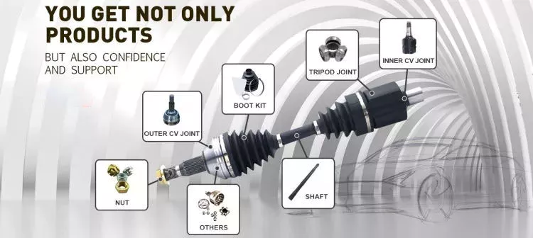
How do drive shafts ensure efficient power transfer while maintaining balance?
Drive shafts employ various mechanisms to ensure efficient power transfer while maintaining balance. Efficient power transfer refers to the ability of the drive shaft to transmit rotational power from the source (such as an engine) to the driven components (such as wheels or machinery) with minimal energy loss. Balancing, on the other hand, involves minimizing vibrations and eliminating any uneven distribution of mass that can cause disturbances during operation. Here’s an explanation of how drive shafts achieve both efficient power transfer and balance:
1. Material Selection:
The material selection for drive shafts is crucial for maintaining balance and ensuring efficient power transfer. Drive shafts are commonly made from materials such as steel or aluminum alloys, chosen for their strength, stiffness, and durability. These materials have excellent dimensional stability and can withstand the torque loads encountered during operation. By using high-quality materials, drive shafts can minimize deformation, flexing, and imbalances that could compromise power transmission and generate vibrations.
2. Pertimbangan Reka Bentuk:
The design of the drive shaft plays a significant role in both power transfer efficiency and balance. Drive shafts are engineered to have appropriate dimensions, including diameter and wall thickness, to handle the anticipated torque loads without excessive deflection or vibration. The design also considers factors such as the length of the drive shaft, the number and type of joints (such as universal joints or constant velocity joints), and the use of balancing weights. By carefully designing the drive shaft, manufacturers can achieve optimal power transfer efficiency while minimizing the potential for imbalance-induced vibrations.
3. Balancing Techniques:
Balance is crucial for drive shafts as any imbalance can cause vibrations, noise, and accelerated wear. To maintain balance, drive shafts undergo various balancing techniques during the manufacturing process. Static and dynamic balancing methods are employed to ensure that the mass distribution along the drive shaft is uniform. Static balancing involves adding counterweights at specific locations to offset any weight imbalances. Dynamic balancing is performed by spinning the drive shaft at high speeds and measuring any vibrations. If imbalances are detected, additional adjustments are made to achieve a balanced state. These balancing techniques help minimize vibrations and ensure smooth operation of the drive shaft.
4. Universal Joints and Constant Velocity Joints:
Drive shafts often incorporate universal joints (U-joints) or constant velocity (CV) joints to accommodate misalignment and maintain balance during operation. U-joints are flexible joints that allow for angular movement between shafts. They are typically used in applications where the drive shaft operates at varying angles. CV joints, on the other hand, are designed to maintain a constant velocity of rotation and are commonly used in front-wheel-drive vehicles. By incorporating these joints, drive shafts can compensate for misalignment, reduce stress on the shaft, and minimize vibrations that can negatively impact power transfer efficiency and balance.
5. Maintenance and Inspection:
Regular maintenance and inspection of drive shafts are essential for ensuring efficient power transfer and balance. Periodic checks for wear, damage, or misalignment can help identify any issues that may affect the drive shaft’s performance. Lubrication of the joints and proper tightening of fasteners are also critical for maintaining optimal operation. By adhering to recommended maintenance procedures, any imbalances or inefficiencies can be addressed promptly, ensuring continued efficient power transfer and balance.
In summary, drive shafts ensure efficient power transfer while maintaining balance through careful material selection, thoughtful design considerations, balancing techniques, and the incorporation of flexible joints. By optimizing these factors, drive shafts can transmit rotational power smoothly and reliably, minimizing energy losses and vibrations that can impact performance and longevity.

How do drive shafts handle variations in load and vibration during operation?
Drive shafts are designed to handle variations in load and vibration during operation by employing various mechanisms and features. These mechanisms help ensure smooth power transmission, minimize vibrations, and maintain the structural integrity of the drive shaft. Here’s a detailed explanation of how drive shafts handle load and vibration variations:
1. Material Selection and Design:
Drive shafts are typically made from materials with high strength and stiffness, such as steel alloys or composite materials. The material selection and design take into account the anticipated loads and operating conditions of the application. By using appropriate materials and optimizing the design, drive shafts can withstand the expected variations in load without experiencing excessive deflection or deformation.
2. Torque Capacity:
Drive shafts are designed with a specific torque capacity that corresponds to the expected loads. The torque capacity takes into account factors such as the power output of the driving source and the torque requirements of the driven components. By selecting a drive shaft with sufficient torque capacity, variations in load can be accommodated without exceeding the drive shaft’s limits and risking failure or damage.
3. Dynamic Balancing:
During the manufacturing process, drive shafts can undergo dynamic balancing. Imbalances in the drive shaft can result in vibrations during operation. Through the balancing process, weights are strategically added or removed to ensure that the drive shaft spins evenly and minimizes vibrations. Dynamic balancing helps to mitigate the effects of load variations and reduces the potential for excessive vibrations in the drive shaft.
4. Dampers and Vibration Control:
Drive shafts can incorporate dampers or vibration control mechanisms to further minimize vibrations. These devices are typically designed to absorb or dissipate vibrations that may arise from load variations or other factors. Dampers can be in the form of torsional dampers, rubber isolators, or other vibration-absorbing elements strategically placed along the drive shaft. By managing and attenuating vibrations, drive shafts ensure smooth operation and enhance overall system performance.
5. CV Joints:
Constant Velocity (CV) joints are often used in drive shafts to accommodate variations in operating angles and to maintain a constant speed. CV joints allow the drive shaft to transmit power even when the driving and driven components are at different angles. By accommodating variations in operating angles, CV joints help minimize the impact of load variations and reduce potential vibrations that may arise from changes in the driveline geometry.
6. Lubrication and Maintenance:
Proper lubrication and regular maintenance are essential for drive shafts to handle load and vibration variations effectively. Lubrication helps reduce friction between moving parts, minimizing wear and heat generation. Regular maintenance, including inspection and lubrication of joints, ensures that the drive shaft remains in optimal condition, reducing the risk of failure or performance degradation due to load variations.
7. Structural Rigidity:
Drive shafts are designed to have sufficient structural rigidity to resist bending and torsional forces. This rigidity helps maintain the integrity of the drive shaft when subjected to load variations. By minimizing deflection and maintaining structural integrity, the drive shaft can effectively transmit power and handle variations in load without compromising performance or introducing excessive vibrations.
8. Control Systems and Feedback:
In some applications, drive shafts may be equipped with control systems that actively monitor and adjust parameters such as torque, speed, and vibration. These control systems use sensors and feedback mechanisms to detect variations in load or vibrations and make real-time adjustments to optimize performance. By actively managing load variations and vibrations, drive shafts can adapt to changing operating conditions and maintain smooth operation.
In summary, drive shafts handle variations in load and vibration during operation through careful material selection and design, torque capacity considerations, dynamic balancing, integration of dampers and vibration control mechanisms, utilization of CV joints, proper lubrication and maintenance, structural rigidity, and, in some cases, control systems and feedback mechanisms. By incorporating these features and mechanisms, drive shafts ensure reliable and efficient power transmission while minimizing the impact of load variations and vibrations on overall system performance.
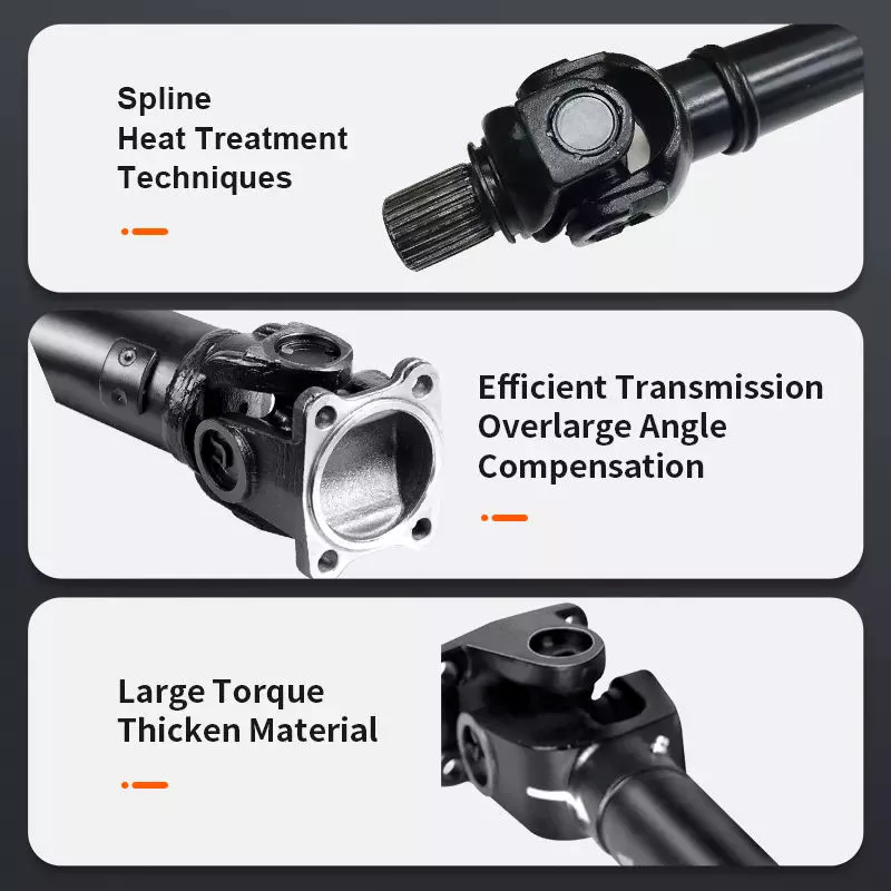
Bagaimanakah aci pemacu menyumbang kepada pemindahan kuasa putaran dalam pelbagai aplikasi?
Aci pacu memainkan peranan penting dalam memindahkan kuasa putaran dari enjin atau sumber kuasa ke roda atau komponen yang digerakkan dalam pelbagai aplikasi. Sama ada dalam kenderaan atau jentera, aci pacu membolehkan penghantaran kuasa yang cekap dan memudahkan fungsi sistem yang berbeza. Berikut ialah penjelasan terperinci tentang bagaimana aci pacu menyumbang kepada pemindahan kuasa putaran:
1. Aplikasi Kenderaan:
Dalam kenderaan, aci pacu bertanggungjawab untuk menghantar kuasa putaran dari enjin ke roda, membolehkan kenderaan bergerak. Aci pacu menghubungkan kotak gear atau aci output transmisi ke pembezaan, yang seterusnya mengagihkan kuasa ke roda. Apabila enjin menjana tork, ia dipindahkan melalui aci pacu ke roda, mendorong kenderaan ke hadapan. Pemindahan kuasa ini membolehkan kenderaan memecut, mengekalkan kelajuan dan mengatasi rintangan, seperti geseran dan cerun.
2. Aplikasi Jentera:
Dalam jentera, aci pacu digunakan untuk memindahkan kuasa putaran dari enjin atau motor ke pelbagai komponen pemacu. Contohnya, dalam jentera perindustrian, aci pacu boleh digunakan untuk menghantar kuasa ke pam, penjana, penghantar atau sistem mekanikal lain. Dalam jentera pertanian, aci pacu biasanya digunakan untuk menyambungkan sumber kuasa ke peralatan seperti mesin penuai, mesin pembalut atau sistem pengairan. Aci pacu membolehkan mesin ini melaksanakan fungsi yang dimaksudkan dengan menghantar kuasa putaran kepada komponen yang diperlukan.
3. Penghantaran Kuasa:
Aci pemacu direka bentuk untuk menghantar kuasa putaran dengan cekap dan andal. Ia mampu memindahkan sejumlah besar tork dari enjin ke roda atau komponen yang digerakkan. Tork yang dihasilkan oleh enjin dihantar melalui aci pemacu tanpa kehilangan kuasa yang ketara. Dengan mengekalkan sambungan yang tegar antara enjin dan komponen yang digerakkan, aci pemacu memastikan bahawa kuasa yang dihasilkan oleh enjin digunakan secara berkesan dalam melaksanakan kerja yang berguna.
4. Gandingan Fleksibel:
Salah satu fungsi utama aci pemacu adalah untuk menyediakan gandingan fleksibel antara enjin/transmisi dan roda atau komponen yang dipacu. Fleksibiliti ini membolehkan aci pemacu menampung pergerakan sudut dan mengimbangi ketidaksejajaran antara enjin dan sistem yang dipacu. Dalam kenderaan, apabila sistem gantungan bergerak atau roda menghadapi rupa bumi yang tidak rata, aci pemacu melaraskan panjang dan sudutnya untuk mengekalkan pemindahan kuasa yang berterusan. Fleksibiliti ini membantu mencegah tekanan berlebihan pada komponen drivetrain dan memastikan penghantaran kuasa yang lancar.
5. Tork dan Kelajuan Penghantaran:
Aci pemacu bertanggungjawab untuk menghantar kedua-dua tork dan kelajuan putaran. Tork ialah daya putaran yang dijana oleh enjin atau sumber kuasa, manakala kelajuan putaran ialah bilangan pusingan seminit (RPM). Aci pemacu mesti mampu mengendalikan keperluan tork aplikasi tanpa putaran atau lenturan yang berlebihan. Di samping itu, ia perlu mengekalkan kelajuan putaran yang diingini untuk memastikan komponen pemacu berfungsi dengan betul. Reka bentuk yang betul, pemilihan bahan dan pengimbangan aci pemacu menyumbang kepada penghantaran tork dan kelajuan yang cekap.
6. Panjang dan Imbangan:
Panjang dan keseimbangan aci pemacu adalah faktor kritikal dalam prestasinya. Panjang aci pemacu ditentukan oleh jarak antara enjin atau sumber kuasa dan komponen yang digerakkan. Saiznya hendaklah sesuai untuk mengelakkan getaran atau lenturan yang berlebihan. Aci pemacu diseimbangkan dengan teliti untuk meminimumkan getaran dan ketidakseimbangan putaran, yang boleh menjejaskan prestasi keseluruhan, keselesaan dan jangka hayat sistem rangkaian pemacu.
7. Keselamatan dan Penyelenggaraan:
Aci pacu memerlukan langkah keselamatan yang betul dan penyelenggaraan berkala. Dalam kenderaan, aci pacu sering disertakan dalam tiub atau perumah pelindung untuk mengelakkan sentuhan dengan bahagian yang bergerak, sekali gus mengurangkan risiko kecederaan. Perisai atau pelindung keselamatan juga boleh dipasang di sekitar aci pacu yang terdedah dalam jentera untuk melindungi pengendali daripada potensi bahaya. Penyelenggaraan berkala termasuk memeriksa aci pacu untuk haus, kerosakan atau ketidaksejajaran, dan memastikan pelinciran sendi-U yang betul. Langkah-langkah ini membantu mencegah kegagalan, memastikan prestasi optimum dan memanjangkan hayat perkhidmatan aci pacu.
Secara ringkasnya, aci pacu memainkan peranan penting dalam memindahkan kuasa putaran dalam pelbagai aplikasi. Sama ada dalam kenderaan atau jentera, aci pacu membolehkan penghantaran kuasa yang cekap dari enjin atau sumber kuasa ke roda atau komponen yang digerakkan. Ia menyediakan gandingan fleksibel, mengendalikan transmisi tork dan kelajuan, menampung pergerakan sudut dan menyumbang kepada keselamatan dan penyelenggaraan sistem. Dengan memindahkan kuasa putaran secara berkesan, aci pacu memudahkan fungsi dan prestasi kenderaan dan jentera dalam pelbagai industri.


editor by CX 2024-04-17

























