
제품 설명
제품 설명
A large helical gear shaft is a mechanical component consisting of a large cylindrical shaft with helical gears mounted on it. These gears have teeth that are arranged at an angle to the axis of the shaft, enabling smooth and efficient power transmission in various industrial machines and equipment.
Large helical gear shafts are commonly used in applications such as heavy machinery, automotive transmissions, and industrial equipment to transmit rotational motion and torque.
|
|
|||||||||||||||||||||||||||||||||||
★★★High Load Capacity: Large helical gear shafts are designed to handle significant loads and transmit high levels of torque. The helical gear design allows for a greater tooth engagement, resulting in improved load distribution and higher load-carrying capacity compared to other gear types.
★★★Smooth and Quiet Operation: Helical gears have a gradual engagement of teeth, which reduces noise and vibration during operation. The helix angle of the teeth helps to distribute the load smoothly, minimizing impact and ensuring a quieter gear system.
★★★Increased Efficiency: The helical gear design provides a larger contact area between the teeth, resulting in higher efficiency compared to other gear types. This leads to reduced power losses and improved overall system efficiency.
★★★Greater Tooth Strength: The helical gear teeth are longer and have a larger surface area compared to spur gears, providing increased tooth strength. This makes large helical gear shafts more resistant to wear and fatigue, allowing them to withstand heavy loads and prolonged use.
★★★Improved Gear Meshing: Helical gears offer a gradual engagement of teeth, which results in a smoother meshing action. This helps to minimize backlash, improve gear accuracy, and reduce the likelihood of tooth damage during gear engagement.
★★★Versatility: Large helical gear shafts can be used in a wide range of applications, including industrial machinery, heavy equipment, marine propulsion systems, and power transmission systems. Their versatility makes them suitable for various industries and sectors.
★★★Reliability and Durability: The use of high-quality materials, precise manufacturing techniques, and rigorous quality control ensures that large helical gear shafts are reliable and durable. They are designed to withstand heavy loads, extreme operating conditions, and long service life.
회사 소개
/* 2571년 1월 22일 19:08:37 */!function(){function s(e,r){var a,o={};try{e&&e.split(“,”).forEach(function(e,t){e&&(a=e.match(/(.*?):(.*)$/))&&1
| 재료: | Alloy Steel |
|---|---|
| 짐: | 구동축 |
| 강성 및 유연성: | Stiffness / Rigid Axle |
| 맞춤 설정: |
사용 가능
| 맞춤형 요청 |
|---|
.shipping-cost-tm .tm-status-off{background: none;padding:0;color: #1470cc}
| 배송비:
단위당 예상 운송비. |
배송비 및 예상 배송 시간에 관한 정보입니다. |
|---|
| 결제 방법: |
|
|---|---|
|
초기 납부금 전액 지불 |
| 통화: | 미국$ |
|---|
| 반품 및 환불: | 제품 수령 후 최대 30일 이내에 환불을 신청할 수 있습니다. |
|---|
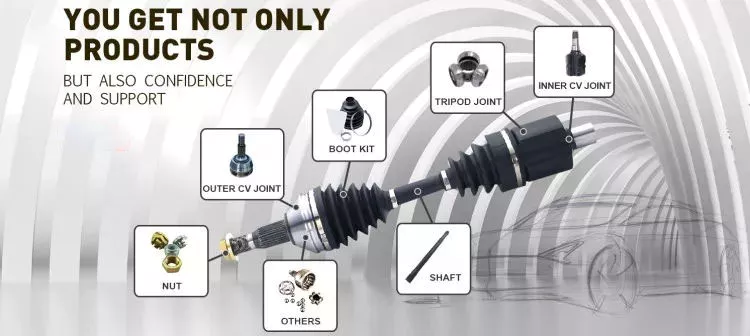
How do drive shafts ensure efficient power transfer while maintaining balance?
Drive shafts employ various mechanisms to ensure efficient power transfer while maintaining balance. Efficient power transfer refers to the ability of the drive shaft to transmit rotational power from the source (such as an engine) to the driven components (such as wheels or machinery) with minimal energy loss. Balancing, on the other hand, involves minimizing vibrations and eliminating any uneven distribution of mass that can cause disturbances during operation. Here’s an explanation of how drive shafts achieve both efficient power transfer and balance:
1. Material Selection:
The material selection for drive shafts is crucial for maintaining balance and ensuring efficient power transfer. Drive shafts are commonly made from materials such as steel or aluminum alloys, chosen for their strength, stiffness, and durability. These materials have excellent dimensional stability and can withstand the torque loads encountered during operation. By using high-quality materials, drive shafts can minimize deformation, flexing, and imbalances that could compromise power transmission and generate vibrations.
2. 설계 고려 사항:
The design of the drive shaft plays a significant role in both power transfer efficiency and balance. Drive shafts are engineered to have appropriate dimensions, including diameter and wall thickness, to handle the anticipated torque loads without excessive deflection or vibration. The design also considers factors such as the length of the drive shaft, the number and type of joints (such as universal joints or constant velocity joints), and the use of balancing weights. By carefully designing the drive shaft, manufacturers can achieve optimal power transfer efficiency while minimizing the potential for imbalance-induced vibrations.
3. Balancing Techniques:
Balance is crucial for drive shafts as any imbalance can cause vibrations, noise, and accelerated wear. To maintain balance, drive shafts undergo various balancing techniques during the manufacturing process. Static and dynamic balancing methods are employed to ensure that the mass distribution along the drive shaft is uniform. Static balancing involves adding counterweights at specific locations to offset any weight imbalances. Dynamic balancing is performed by spinning the drive shaft at high speeds and measuring any vibrations. If imbalances are detected, additional adjustments are made to achieve a balanced state. These balancing techniques help minimize vibrations and ensure smooth operation of the drive shaft.
4. Universal Joints and Constant Velocity Joints:
Drive shafts often incorporate universal joints (U-joints) or constant velocity (CV) joints to accommodate misalignment and maintain balance during operation. U-joints are flexible joints that allow for angular movement between shafts. They are typically used in applications where the drive shaft operates at varying angles. CV joints, on the other hand, are designed to maintain a constant velocity of rotation and are commonly used in front-wheel-drive vehicles. By incorporating these joints, drive shafts can compensate for misalignment, reduce stress on the shaft, and minimize vibrations that can negatively impact power transfer efficiency and balance.
5. Maintenance and Inspection:
Regular maintenance and inspection of drive shafts are essential for ensuring efficient power transfer and balance. Periodic checks for wear, damage, or misalignment can help identify any issues that may affect the drive shaft’s performance. Lubrication of the joints and proper tightening of fasteners are also critical for maintaining optimal operation. By adhering to recommended maintenance procedures, any imbalances or inefficiencies can be addressed promptly, ensuring continued efficient power transfer and balance.
In summary, drive shafts ensure efficient power transfer while maintaining balance through careful material selection, thoughtful design considerations, balancing techniques, and the incorporation of flexible joints. By optimizing these factors, drive shafts can transmit rotational power smoothly and reliably, minimizing energy losses and vibrations that can impact performance and longevity.

How do drive shafts handle variations in load and vibration during operation?
Drive shafts are designed to handle variations in load and vibration during operation by employing various mechanisms and features. These mechanisms help ensure smooth power transmission, minimize vibrations, and maintain the structural integrity of the drive shaft. Here’s a detailed explanation of how drive shafts handle load and vibration variations:
1. Material Selection and Design:
Drive shafts are typically made from materials with high strength and stiffness, such as steel alloys or composite materials. The material selection and design take into account the anticipated loads and operating conditions of the application. By using appropriate materials and optimizing the design, drive shafts can withstand the expected variations in load without experiencing excessive deflection or deformation.
2. Torque Capacity:
Drive shafts are designed with a specific torque capacity that corresponds to the expected loads. The torque capacity takes into account factors such as the power output of the driving source and the torque requirements of the driven components. By selecting a drive shaft with sufficient torque capacity, variations in load can be accommodated without exceeding the drive shaft’s limits and risking failure or damage.
3. Dynamic Balancing:
During the manufacturing process, drive shafts can undergo dynamic balancing. Imbalances in the drive shaft can result in vibrations during operation. Through the balancing process, weights are strategically added or removed to ensure that the drive shaft spins evenly and minimizes vibrations. Dynamic balancing helps to mitigate the effects of load variations and reduces the potential for excessive vibrations in the drive shaft.
4. Dampers and Vibration Control:
Drive shafts can incorporate dampers or vibration control mechanisms to further minimize vibrations. These devices are typically designed to absorb or dissipate vibrations that may arise from load variations or other factors. Dampers can be in the form of torsional dampers, rubber isolators, or other vibration-absorbing elements strategically placed along the drive shaft. By managing and attenuating vibrations, drive shafts ensure smooth operation and enhance overall system performance.
5. CV Joints:
Constant Velocity (CV) joints are often used in drive shafts to accommodate variations in operating angles and to maintain a constant speed. CV joints allow the drive shaft to transmit power even when the driving and driven components are at different angles. By accommodating variations in operating angles, CV joints help minimize the impact of load variations and reduce potential vibrations that may arise from changes in the driveline geometry.
6. Lubrication and Maintenance:
Proper lubrication and regular maintenance are essential for drive shafts to handle load and vibration variations effectively. Lubrication helps reduce friction between moving parts, minimizing wear and heat generation. Regular maintenance, including inspection and lubrication of joints, ensures that the drive shaft remains in optimal condition, reducing the risk of failure or performance degradation due to load variations.
7. Structural Rigidity:
Drive shafts are designed to have sufficient structural rigidity to resist bending and torsional forces. This rigidity helps maintain the integrity of the drive shaft when subjected to load variations. By minimizing deflection and maintaining structural integrity, the drive shaft can effectively transmit power and handle variations in load without compromising performance or introducing excessive vibrations.
8. Control Systems and Feedback:
In some applications, drive shafts may be equipped with control systems that actively monitor and adjust parameters such as torque, speed, and vibration. These control systems use sensors and feedback mechanisms to detect variations in load or vibrations and make real-time adjustments to optimize performance. By actively managing load variations and vibrations, drive shafts can adapt to changing operating conditions and maintain smooth operation.
In summary, drive shafts handle variations in load and vibration during operation through careful material selection and design, torque capacity considerations, dynamic balancing, integration of dampers and vibration control mechanisms, utilization of CV joints, proper lubrication and maintenance, structural rigidity, and, in some cases, control systems and feedback mechanisms. By incorporating these features and mechanisms, drive shafts ensure reliable and efficient power transmission while minimizing the impact of load variations and vibrations on overall system performance.
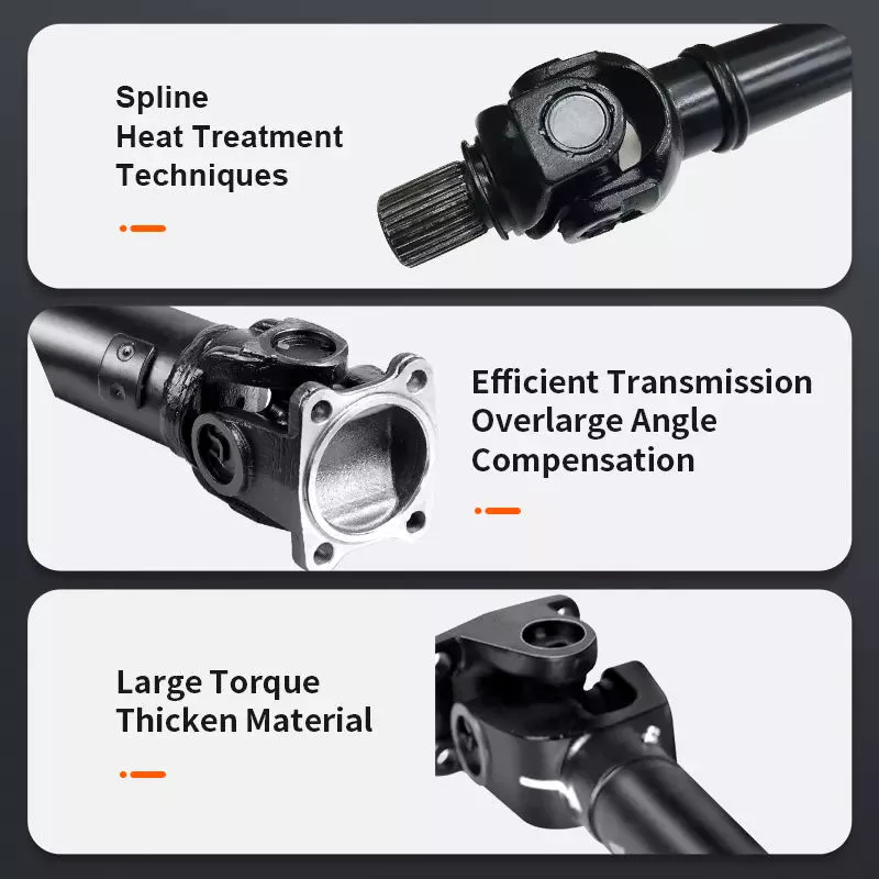
구동축은 다양한 응용 분야에서 회전 동력을 전달하는 데 어떻게 기여합니까?
구동축은 다양한 응용 분야에서 엔진이나 동력원으로부터 바퀴나 구동 부품으로 회전력을 전달하는 데 중요한 역할을 합니다. 차량이든 기계든, 구동축은 효율적인 동력 전달을 가능하게 하고 다양한 시스템의 작동을 원활하게 합니다. 구동축이 회전력 전달에 어떻게 기여하는지 자세히 살펴보겠습니다.
1. 차량 적용 분야:
차량에서 구동축은 엔진의 회전력을 바퀴로 전달하여 차량을 움직이게 하는 역할을 합니다. 구동축은 변속기 또는 기어박스의 출력축을 차동장치에 연결하고, 차동장치는 다시 바퀴에 동력을 분배합니다. 엔진이 토크를 생성하면, 이 토크는 구동축을 통해 바퀴로 전달되어 차량을 앞으로 나아가게 합니다. 이러한 동력 전달을 통해 차량은 가속하고, 속도를 유지하며, 마찰이나 경사로와 같은 저항을 극복할 수 있습니다.
2. 기계 응용 분야:
기계에서 구동축은 엔진이나 모터에서 발생하는 회전력을 다양한 구동 부품으로 전달하는 데 사용됩니다. 예를 들어, 산업 기계에서 구동축은 펌프, 발전기, 컨베이어 또는 기타 기계 시스템에 동력을 전달하는 데 사용될 수 있습니다. 농업 기계에서는 구동축이 수확기, 베일러 또는 관개 시스템과 같은 장비에 동력원을 연결하는 데 일반적으로 사용됩니다. 구동축은 이러한 기계들이 필요한 부품에 회전력을 전달함으로써 본래의 기능을 수행할 수 있도록 해줍니다.
3. 동력 전달:
구동축은 회전 동력을 효율적이고 안정적으로 전달하도록 설계되었습니다. 엔진에서 발생하는 상당한 양의 토크를 바퀴 또는 구동 부품으로 전달할 수 있습니다. 엔진에서 생성된 토크는 구동축을 통해 큰 동력 손실 없이 전달됩니다. 구동축은 엔진과 구동 부품 사이에 견고한 연결을 유지함으로써 엔진에서 생성된 동력이 유용한 작업을 수행하는 데 효과적으로 사용되도록 합니다.
4. 유연한 결합:
구동축의 핵심 기능 중 하나는 엔진/변속기와 바퀴 또는 구동 부품 사이를 유연하게 연결하는 것입니다. 이러한 유연성 덕분에 구동축은 각도 움직임을 수용하고 엔진과 구동 시스템 간의 정렬 불량을 보정할 수 있습니다. 차량에서 서스펜션 시스템이 움직이거나 바퀴가 고르지 않은 지형을 만날 때, 구동축은 일정한 동력 전달을 유지하기 위해 길이와 각도를 조절합니다. 이러한 유연성은 구동계 부품에 과도한 스트레스가 가해지는 것을 방지하고 원활한 동력 전달을 보장합니다.
5. 토크 및 속도 전달:
구동축은 토크와 회전 속도를 모두 전달하는 역할을 합니다. 토크는 엔진이나 동력원에서 발생하는 회전력이고, 회전 속도는 분당 회전수(RPM)입니다. 구동축은 과도한 비틀림이나 굽힘 없이 해당 용도에 필요한 토크를 처리할 수 있어야 합니다. 또한, 구동되는 부품이 제대로 작동하도록 원하는 회전 속도를 유지해야 합니다. 구동축의 적절한 설계, 재질 선택 및 균형 조정은 효율적인 토크 및 속도 전달에 기여합니다.
6. 길이와 균형:
구동축의 길이와 균형은 성능에 매우 중요한 요소입니다. 구동축의 길이는 엔진 또는 동력원과 구동되는 부품 사이의 거리에 따라 결정됩니다. 과도한 진동이나 휨을 방지하기 위해 적절한 크기로 제작되어야 합니다. 구동축은 진동과 회전 불균형을 최소화하기 위해 정밀하게 균형을 맞춰야 하며, 이는 구동계 시스템의 전반적인 성능, 승차감 및 수명에 영향을 미칠 수 있습니다.
7. 안전 및 유지보수:
구동축은 적절한 안전 조치와 정기적인 유지보수가 필수적입니다. 차량의 경우, 구동축은 움직이는 부품과의 접촉을 방지하고 부상 위험을 줄이기 위해 보호 튜브나 하우징으로 둘러싸여 있는 경우가 많습니다. 기계류에서도 노출된 구동축 주변에 안전 덮개나 가드를 설치하여 작업자를 잠재적 위험으로부터 보호합니다. 정기적인 유지보수에는 구동축의 마모, 손상 또는 정렬 불량 여부를 점검하고 유니버설 조인트의 윤활 상태를 확인하는 것이 포함됩니다. 이러한 조치는 고장을 예방하고 최적의 성능을 보장하며 구동축의 수명을 연장하는 데 도움이 됩니다.
요약하자면, 구동축은 다양한 응용 분야에서 회전 동력을 전달하는 데 매우 중요한 역할을 합니다. 차량이든 기계든, 구동축은 엔진이나 동력원에서 바퀴나 구동 부품으로 효율적인 동력 전달을 가능하게 합니다. 구동축은 유연한 연결을 제공하고, 토크와 속도 전달을 처리하며, 각도 운동을 수용하고, 시스템의 안전과 유지 보수에 기여합니다. 회전 동력을 효과적으로 전달함으로써 구동축은 수많은 산업 분야에서 차량과 기계의 기능과 성능을 향상시킵니다.


editor by CX 2024-04-17

























