
Deskripsi Produk
Product Details
A coupling is a mechanical component that is used to firmly connect the driving shaft and driven shaft in different mechanisms together, rotate together, and transmit motion and torque. It is also sometimes used to connect shafts and other parts (e.g. gears, pulleys, etc.). It usually consists of 2 parts, which are connected by a key or clamping fit, respectively, and fastened at the 2 shaft ends. Couplings can compensate for deviations (including axial, radial, angular or combined offset) between 2 shafts due to inaccurate manufacturing and installation, deformation or thermal expansion during operation, as well as shock and vibration absorption. The most commonly used couplings have been standardized or normalized. In general, it is only necessary to select the type of coupling correctly and determine the type and size of the coupling. If necessary, check and calculate the carrying capacity of the vulnerable and weak links; When the rotational speed is high, it is necessary to check the centrifugal force on the outer edge and the deformation of the elastic element for balance detection.
Couplings are used to connect shafts in different mechanisms, mainly by rotation, thus transferring torque. Under the action of high-speed power, the coupling has the function of buffering and damping, and the coupling has good service life and working efficiency.
The function of the coupling:
a device that connects 2 shafts or shafts with rotating parts and rotates together in the process of transmitting motion and power and does not break away under normal circumstances. Sometimes, it is also used as a safety device to prevent the connected parts from bearing excessive loads and play the role of overload protection. The coupling is installed between the active side and the passive side of the power transmission, which plays the role of transferring torque, compensating the installation deviation between shafts, absorbing equipment vibration and buffering load impact. One of the functions of couplings is to absorb and compensate for deviations between shafts through their own deformation. The greater the elasticity, the stronger the ability to absorb the deviation; The less flexibility you have, the less ability you have to absorb deviations. In general, the deviation between the shaft and the shaft can be divided into the following 3 aspects: The connection between the coupling and the peripheral equipment is achieved by inserting the shaft of the device into the shaft hole of the coupling.
1. The role of the coupling is to connect the 2 shafts in different mechanisms (drive shaft and driven shaft) to rotate and transmit torque together, and some couplings also have the role of buffering, damping and improving the dynamic performance of the shafting.
2. Eliminate the inertia of the radial force, connect the motor spindle with the load, and use a coupling to weaken the starting power when the motor starts.
3. Power conduction, transmission of power and torque (improve the performance of the transmission system)
4. Different degrees of vibration reduction and buffering
5. Disconnect when the load is too large to play a protective role
6. Good for maintenance
7. Change the drive direction
8. Concentricity correction (different degrees of axial, radial and angular compensation performance)
The types of couplings
Bellows coupling
The bellows coupling is composed of 2 hubs and thin-walled bellows that are welded or bonded together. The input end of the coupling structure is a clamping structure, and the pre-tightening force is generated by clamping screws, and the power input shaft is firmly connected with the clamping hoop. Flexible and rigid stainless steel bellows have the ability to correct radial, axial and angular deviations, transmit torque with zero backlash, and have different bushings designed to meet different equipment requirements.
A plum coupling
Plum coupling is a widely used coupling, elastomer is a balance accessory, can zero back backlash transfer torque and shock absorption. The different types of elastomers determine the characteristics of the entire drive system. Zero back backlash is achieved through a pre-pressure between the 2 coupling bushing and the elastomer. Its elastomer is usually composed of engineering plastics or rubber. Because elastomers have the function of buffering and reducing vibration, they are widely used in the case of strong vibration.
Safety coupling
The safety coupling mainly relies on the spring force and works with the shape, which can protect the adjacent drive components from damage caused by overload. Divided into synchronous type, stepping type 60°, failure protection type, closed. Features of a special butterfly spring system. No torque transfer is possible until the torque control nut is linked to the butterfly spring to apply pressure. The service life of the safety coupling is largely determined by the speed at which the coupling is disengaged and the holding time of the coupling. The safety coupling is not worn when it is engaged, does not require maintenance, and does not require additional refueling.
Rigid coupling
The rigid coupling is actually a torsional rigid coupling. Even under load, there is no turning clearance. Even if there is a deviation that creates a load, the rigid coupling is still rigid to transmit torque. Rigid couplings need to be used to connect 2 shafts in strict alignment without relative misalignment, so they are used less in motor test systems. Of course, if the relative displacement can be successfully controlled (the alignment accuracy is high enough), rigid coupling can also play an excellent role in the application. In particular, the small size rigid coupling has the advantages of light weight, ultra-low inertia and high sensitivity. In practical applications, rigid couplings have the advantages of maintenance-free, ultra-oil resistance and corrosion resistance.
Long shaft coupling
The standard length of the long-shaft coupling is up to 6 meters, and no intermediate support is required. The 2 ends are connected by high-performance stainless steel or high-strength aluminum, and the middle pipe is made of different materials such as steel, aluminum or carbon fiber. The allowable deviation range, speed and torque of the standard model should be reduced by 30%. The allowable working speed depends on the total length of the joint shaft and can also be adjusted according to demand.
Diaphragm coupling
Diaphragm couplings transfer torque by friction and diaphragm assembly, so there are no stress concentrations, backbacklash and micro-displacement that occur when torque is transferred through shoulder bolts. It has a near unlimited service life and increases the torsional rigidity of the individual components of the complete coupling, which can compensate for a variety of combined shaft assembly errors as a percentage of the total allowable error value listed in the data sheet. The sum of the percentages of the 3 errors cannot exceed 100%.
Deskripsi Produk
Sebagai seorang profesional pabrikan untuk poros baling-baling, kita punya +1000 items for all kinds of car, At present, our products are mainly sold in North America, Europe, Australia, South Korea, the Middle East and Southeast Asia and other regions, applicable models are European cars, American cars, Japanese and Korean cars, etc. /* January 22, 2571 19:08:37 */!function(){function s(e,r){var a,o={};try{e&&e.split(“,”).forEach(function(e,t){e&&(a=e.match(/(.*?):(.*)$/))&&1
| Standard Or Nonstandard: | Standard |
|---|---|
| Torque: | >80N.M |
| Bore Diameter: | According to Specific Drawings |
| Kustomisasi: |
Tersedia
| Permintaan Khusus |
|---|
.shipping-cost-tm .tm-status-off{background: none;padding:0;color: #1470cc}
|
Biaya Pengiriman:
Perkiraan biaya pengiriman per unit. |
tentang biaya pengiriman dan perkiraan waktu pengiriman. |
|---|
| Metode Pembayaran: |
|
|---|---|
|
Pembayaran Awal Pembayaran Penuh |
| Mata uang: | US$ |
|---|
| Pengembalian & Penggantian Dana: | Anda dapat mengajukan pengembalian dana hingga 30 hari setelah menerima produk. |
|---|
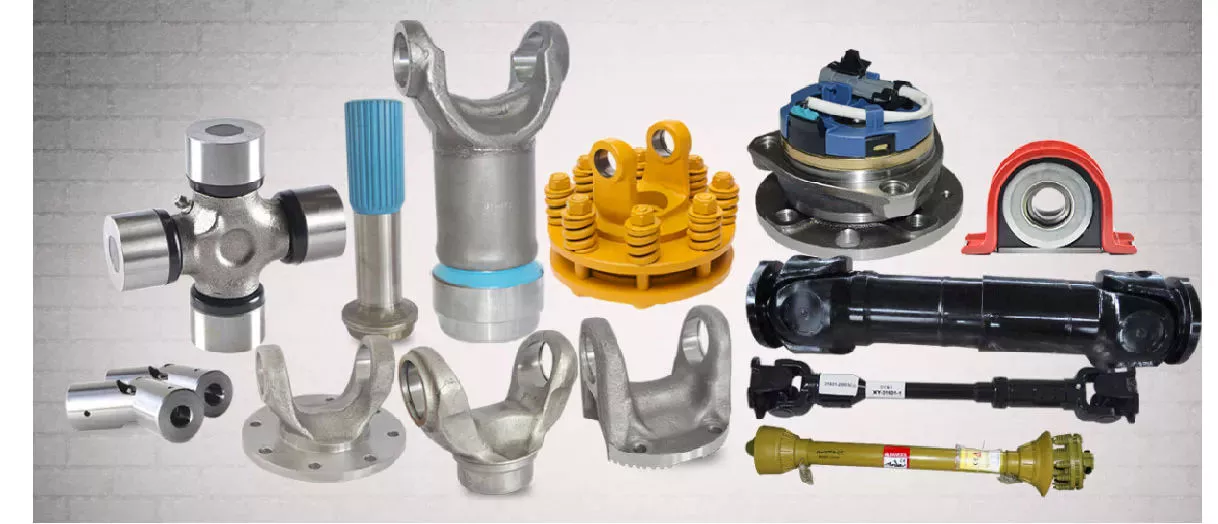
Faktor apa saja yang perlu dipertimbangkan saat memilih poros penggerak yang tepat untuk suatu aplikasi?
Saat memilih poros penggerak yang tepat untuk suatu aplikasi, beberapa faktor perlu dipertimbangkan. Pilihan poros penggerak memainkan peran penting dalam memastikan transmisi daya yang efisien dan andal. Berikut adalah faktor-faktor kunci yang perlu dipertimbangkan:
1. Persyaratan Daya dan Torsi:
Persyaratan daya dan torsi aplikasi merupakan pertimbangan penting. Sangat penting untuk menentukan torsi maksimum yang perlu ditransmisikan oleh poros penggerak tanpa mengalami kegagalan atau defleksi berlebihan. Ini termasuk mengevaluasi daya keluaran mesin atau sumber daya, serta kebutuhan torsi dari komponen yang digerakkan. Memilih poros penggerak dengan diameter, kekuatan material, dan desain yang sesuai sangat penting untuk memastikan poros tersebut dapat menangani tingkat torsi yang diharapkan tanpa mengorbankan kinerja atau keselamatan.
2. Kecepatan Operasi:
Kecepatan operasi poros penggerak merupakan faktor penting lainnya. Kecepatan putaran memengaruhi perilaku dinamis poros penggerak, termasuk potensi getaran, resonansi, dan batasan kecepatan kritis. Penting untuk memilih poros penggerak yang dapat beroperasi dalam rentang kecepatan yang diinginkan tanpa mengalami getaran berlebihan atau mengganggu integritas struktural. Faktor-faktor seperti sifat material, keseimbangan, dan analisis kecepatan kritis harus dipertimbangkan untuk memastikan poros penggerak dapat menangani kecepatan operasi yang dibutuhkan secara efektif.
3. Panjang dan Penyelarasan:
Persyaratan panjang dan penyelarasan aplikasi harus dipertimbangkan saat memilih poros penggerak. Jarak antara mesin atau sumber daya dan komponen yang digerakkan menentukan panjang poros penggerak yang dibutuhkan. Dalam situasi di mana terdapat variasi panjang atau sudut operasi yang signifikan, poros penggerak teleskopik atau beberapa poros penggerak dengan kopling atau sambungan universal yang sesuai mungkin diperlukan. Penyelarasan poros penggerak yang tepat sangat penting untuk meminimalkan getaran, mengurangi keausan, dan memastikan transmisi daya yang efisien.
4. Keterbatasan Ruang:
Ruang yang tersedia dalam aplikasi merupakan faktor penting yang perlu dipertimbangkan. Poros penggerak harus sesuai dengan ruang yang dialokasikan tanpa mengganggu komponen atau struktur lain. Sangat penting untuk mempertimbangkan dimensi keseluruhan poros penggerak, termasuk panjang, diameter, dan komponen tambahan apa pun seperti sambungan atau kopling. Dalam beberapa kasus, desain poros penggerak khusus atau kompak mungkin diperlukan untuk mengakomodasi keterbatasan ruang sambil mempertahankan kemampuan transmisi daya yang memadai.
5. Kondisi Lingkungan:
Kondisi lingkungan tempat poros penggerak akan beroperasi harus dievaluasi. Faktor-faktor seperti suhu, kelembapan, zat korosif, dan paparan kontaminan dapat memengaruhi kinerja dan umur pakai poros penggerak. Penting untuk memilih material dan pelapis yang dapat menahan kondisi lingkungan spesifik untuk mencegah korosi, degradasi, atau kegagalan dini pada poros penggerak. Pertimbangan khusus mungkin diperlukan untuk aplikasi yang terpapar suhu ekstrem, air, bahan kimia, atau zat abrasif.
6. Jenis Aplikasi dan Industri:
Jenis aplikasi spesifik dan persyaratan industri memainkan peran penting dalam pemilihan poros penggerak. Industri yang berbeda, seperti otomotif, kedirgantaraan, mesin industri, pertanian, atau kelautan, memiliki tuntutan unik yang perlu dipenuhi. Memahami kebutuhan spesifik dan kondisi operasi aplikasi sangat penting dalam menentukan desain poros penggerak, material, dan karakteristik kinerja yang tepat. Kepatuhan terhadap standar dan peraturan industri juga dapat menjadi pertimbangan dalam aplikasi tertentu.
7. Pemeliharaan dan Kemudahan Servis:
Kemudahan perawatan dan servis harus diperhatikan. Beberapa desain poros penggerak mungkin memerlukan inspeksi berkala, pelumasan, atau penggantian komponen. Mempertimbangkan aksesibilitas poros penggerak dan persyaratan perawatan terkait dapat membantu meminimalkan waktu henti dan memastikan keandalan jangka panjang. Pembongkaran dan pemasangan kembali poros penggerak yang mudah juga dapat bermanfaat untuk perbaikan atau penggantian komponen.
Dengan mempertimbangkan faktor-faktor ini secara cermat, seseorang dapat memilih poros penggerak yang tepat untuk suatu aplikasi yang memenuhi kebutuhan transmisi daya, kondisi operasi, dan persyaratan daya tahan, yang pada akhirnya memastikan kinerja dan keandalan yang optimal.
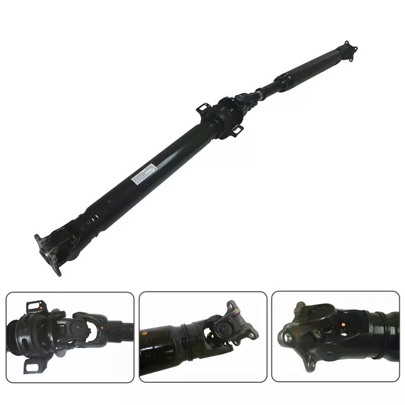
Bisakah Anda memberikan contoh nyata kendaraan dan mesin yang menggunakan poros penggerak?
Poros penggerak banyak digunakan pada berbagai kendaraan dan mesin untuk mentransmisikan daya dari mesin atau sumber daya ke roda atau komponen yang digerakkan. Berikut beberapa contoh nyata kendaraan dan mesin yang menggunakan poros penggerak:
1. Mobil:
Poros penggerak (drive shaft) umumnya ditemukan pada mobil, terutama yang menggunakan sistem penggerak roda belakang atau penggerak empat roda. Pada kendaraan ini, poros penggerak mentransfer daya dari transmisi atau kotak transfer ke diferensial belakang atau diferensial depan. Hal ini memungkinkan daya mesin didistribusikan ke roda, sehingga mendorong kendaraan maju.
2. Truk dan Kendaraan Komersial:
Poros penggerak merupakan komponen penting pada truk dan kendaraan komersial. Poros ini digunakan untuk mentransfer daya dari transmisi atau kotak transfer ke gandar belakang atau beberapa gandar pada truk tugas berat. Poros penggerak pada kendaraan komersial dirancang untuk menangani beban torsi yang lebih tinggi dan seringkali lebih besar dan lebih kuat daripada yang digunakan pada mobil penumpang.
3. Peralatan Konstruksi dan Penggalian Tanah:
Berbagai jenis peralatan konstruksi dan penggalian tanah, seperti ekskavator, loader, bulldozer, dan grader, bergantung pada poros penggerak untuk transmisi daya. Mesin-mesin ini biasanya memiliki sistem penggerak yang kompleks yang menggunakan poros penggerak untuk mentransfer daya dari mesin ke roda atau trek, sehingga memungkinkan mereka untuk melakukan tugas-tugas berat di lokasi konstruksi atau operasi pertambangan.
4. Mesin Pertanian:
Mesin pertanian, termasuk traktor, mesin pemanen gabungan, dan mesin pemanen, menggunakan poros penggerak untuk mentransmisikan daya dari mesin ke roda atau komponen yang digerakkan. Poros penggerak pada mesin pertanian seringkali mengalami kondisi yang berat dan mungkin memiliki fitur tambahan seperti bagian teleskopik untuk mengakomodasi jarak yang bervariasi antar komponen.
5. Mesin Industri:
Mesin-mesin industri, seperti peralatan manufaktur, generator, pompa, dan kompresor, seringkali menggabungkan poros penggerak dalam sistem transmisi dayanya. Poros penggerak ini mentransfer daya dari motor listrik, mesin, atau sumber daya lainnya ke berbagai komponen yang digerakkan, sehingga memungkinkan mesin untuk melakukan tugas-tugas spesifik di lingkungan industri.
6. Kapal Laut:
Dalam aplikasi kelautan, poros penggerak umumnya digunakan untuk mentransmisikan daya dari mesin ke baling-baling pada perahu, kapal, dan kendaraan air lainnya. Poros penggerak kelautan biasanya lebih panjang dan dirancang untuk menahan tantangan unik yang ditimbulkan oleh lingkungan air, termasuk ketahanan terhadap korosi dan mekanisme penyegelan yang sesuai.
7. Kendaraan Rekreasi (RV) dan Motorhome:
Kendaraan rekreasi (RV) dan motorhome sering menggunakan poros penggerak sebagai bagian dari sistem penggeraknya. Poros penggerak ini mentransfer daya dari transmisi ke gandar belakang, memungkinkan kendaraan untuk bergerak dan memberikan tenaga dorong. Poros penggerak pada RV mungkin memiliki fitur tambahan seperti peredam atau komponen peredam getaran untuk meningkatkan kenyamanan selama perjalanan.
8. Kendaraan Off-Road dan Balap:
Kendaraan off-road, seperti SUV, truk, dan kendaraan segala medan (ATV), serta kendaraan balap, sering menggunakan poros penggerak. Poros penggerak ini dirancang untuk menahan kerasnya kondisi off-road atau balap performa tinggi, mentransmisikan daya secara efisien ke roda dan memastikan traksi serta performa yang optimal.
9. Sarana Perkeretaapian:
Dalam sistem perkeretaapian, poros penggerak digunakan pada lokomotif dan beberapa jenis gerbong. Poros ini mentransfer daya dari mesin lokomotif ke roda atau sistem penggerak, memungkinkan kereta untuk bergerak di sepanjang rel. Poros penggerak kereta api biasanya jauh lebih panjang dan mungkin memiliki fitur tambahan untuk mengakomodasi sifat artikulasi atau fleksibel dari beberapa konfigurasi kereta.
10. Turbin Angin:
Turbin angin skala besar yang digunakan untuk menghasilkan listrik menggabungkan poros penggerak dalam sistem transmisi dayanya. Poros penggerak mentransfer energi rotasi dari bilah turbin ke generator, di mana energi tersebut diubah menjadi daya listrik. Poros penggerak pada turbin angin dirancang untuk menangani torsi dan gaya rotasi yang signifikan yang dihasilkan oleh angin.
Contoh-contoh ini menunjukkan beragam kendaraan dan mesin yang bergantung pada poros penggerak untuk transmisi daya dan penggerak yang efisien. Poros penggerak merupakan komponen penting dalam berbagai industri, memungkinkan transfer daya dari sumber ke komponen yang digerakkan, yang pada akhirnya memfasilitasi pergerakan, pengoperasian, atau pelaksanaan tugas-tugas tertentu.
How do drive shafts handle variations in length and torque requirements?
Drive shafts are designed to handle variations in length and torque requirements in order to efficiently transmit rotational power. Here’s an explanation of how drive shafts address these variations:
Length Variations:
Drive shafts are available in different lengths to accommodate varying distances between the engine or power source and the driven components. They can be custom-made or purchased in standardized lengths, depending on the specific application. In situations where the distance between the engine and the driven components is longer, multiple drive shafts with appropriate couplings or universal joints can be used to bridge the gap. These additional drive shafts effectively extend the overall length of the power transmission system.
Additionally, some drive shafts are designed with telescopic sections. These sections can be extended or retracted, allowing for adjustments in length to accommodate different vehicle configurations or dynamic movements. Telescopic drive shafts are commonly used in applications where the distance between the engine and the driven components may change, such as in certain types of trucks, buses, and off-road vehicles.
Torque Requirements:
Drive shafts are engineered to handle varying torque requirements based on the power output of the engine or power source and the demands of the driven components. The torque transmitted through the drive shaft depends on factors such as the engine power, load conditions, and the resistance encountered by the driven components.
Manufacturers consider torque requirements when selecting the appropriate materials and dimensions for drive shafts. Drive shafts are typically made from high-strength materials, such as steel or aluminum alloys, to withstand the torque loads without deformation or failure. The diameter, wall thickness, and design of the drive shaft are carefully calculated to ensure it can handle the expected torque without excessive deflection or vibration.
In applications with high torque demands, such as heavy-duty trucks, industrial machinery, or performance vehicles, drive shafts may have additional reinforcements. These reinforcements can include thicker walls, cross-sectional shapes optimized for strength, or composite materials with superior torque-handling capabilities.
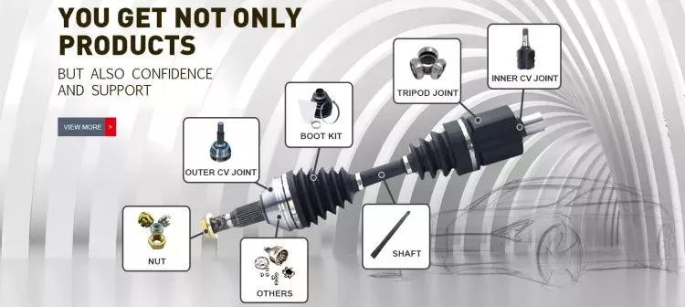
Furthermore, drive shafts often incorporate flexible joints, such as universal joints or constant velocity (CV) joints. These joints allow for angular misalignment and compensate for variations in the operating angles between the engine, transmission, and driven components. They also help absorb vibrations and shocks, reducing stress on the drive shaft and enhancing its torque-handling capacity.
In summary, drive shafts handle variations in length and torque requirements through customizable lengths, telescopic sections, appropriate materials and dimensions, and the inclusion of flexible joints. By carefully considering these factors, drive shafts can efficiently and reliably transmit power while accommodating the specific needs of different applications.


editor by CX 2024-04-16

























