
Produktbeschreibung
ZheJiang WALLONG-HSIN MACHINERY ENGINEERING CORPORATION LTD. short name ‘JSW’, is a wholly state-owned company, also a subsidiary of SINOMACH GROUP (the biggest machinery group in China, ranked No.250 of TOP500 in 2571).
JSW is founded in 1992 and registered with capital of 4.5 million US dollars, located in HangZhou city, ZheJiang Province, with workshop area 50,000 square meters with first-class production lines, and office area 3000 square meters.
JSW passed ISO 9001,ISO 14001,ISO 45001 ,ISO 50001 and AEO custom certified.
The turnover last year is 20 million US dollar,exporting to European, North American, South American, and Asian markets.
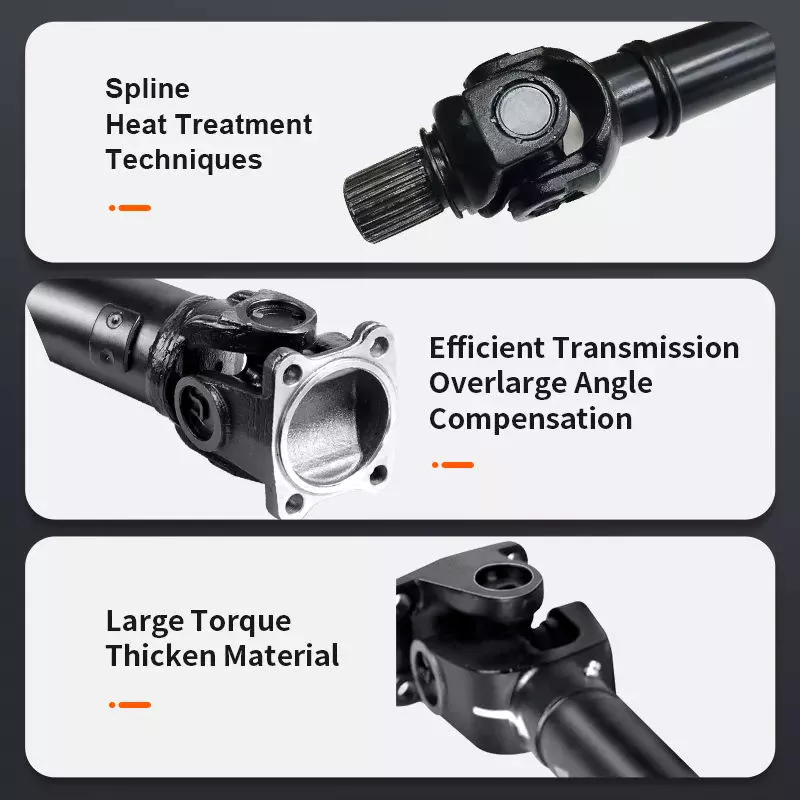
We have successfully developed a wide range and variety of drive shaft products,mainly including PTO agricultural shaft, industrial cardan shaft, drive shaft for automotive, and universal couplings.
Our products are welcomed by all our customers based on our competitive price, guaranteed quality and on-time delivery.
*Agricultural PTO Welle :
Standard series, customized also accpeted.
Tube type:Triangle, Lemon, Star, Spline stub (Z6,Z8,Z20,Z21).
Accessory: various yokes, splined stub shaft, clutch and torque limiter.
*Industrial cardan Welle:
Light duty type: flange Dia. Φ58-180mm
Medium duty type: SWC180 – 550
*Automotive drive Welle :
Aftermarket for ATV,Pickup truck,Light truck
***HOW TO CHOOSE THE SUITABLE PTO SHAFT FOR YOUR DEMANDS?
1. Model/size of the universal joint, which is according to your requirment of maximum torque(TN) and R.P.M.
2. Closed overall length of shaft assembly (or cross (u-joint) to cross length).
3. Shape of the steel tube/pipe (traiangle, lemon, star, splined stub).
4. Type of the 2 end yokes/forks which used to connect the input end (power source) and output end (implement).
Including the series of quick released splined yoke/fork, plain bore yoke/fork, wide-angle yoke/fork, double yoke/fork.
5. Overload protection device including the clutch and torque limitter.
(shear bolt SB, free wheel/overrunning RA/RAS, ratchet SA/SAS, friction FF/FFS)
6. Others requirements:such as with/no plastic guard, painting color, package type,etc.
| Triangle tube type | |||||||
| Serie | Cross kit | Betriebsdrehmoment | |||||
| 540rpm | 1000rpm | ||||||
| Kw | Pk | Nm | Kw | Pk | Nm | ||
| T1 | 1.01 22*54 | 12 | 16 | 210 | 18 | 25 | 172 |
| T2 | 2.01 23.8*61.3 | 15 | 21 | 270 | 23 | 31 | 220 |
| T3 | 3.01 27*70 | 22 | 30 | 390 | 35 | 47 | 330 |
| T4 | 4.01 27*74.6 | 26 | 35 | 460 | 40 | 55 | 380 |
| T5 | 5.01 30.2*80 | 35 | 47 | 620 | 54 | 74 | 520 |
| T6 | 6.01 30.2*92 | 47 | 64 | 830 | 74 | 100 | 710 |
| T7 | 7.01 30.2*106.5 | 55 | 75 | 970 | 87 | 118 | 830 |
| T7N | 7N.01 35*94 | 55 | 75 | 970 | 87 | 118 | 830 |
| T8 | 8.01 35*106.5 | 70 | 95 | 110 | 110 | 150 | 1050 |
| T38 | 38.01 38*105.6 | 78 | 105 | 123 | 123 | 166 | 1175 |
| T9 | 9.01 41*108 | 88 | 120 | 140 | 140 | 190 | 1340 |
| T10 | 10.01 41*118 | 106 | 145 | 179 | 170 | 230 | 1650 |
| Lemon tube type | |||||||
| Serie | Cross kit | Betriebsdrehmoment | |||||
| 540rpm | 1000rpm | ||||||
| Kw | Pk | Nm | Kw | Pk | Nm | ||
| L1 | 1.01 22*54 | 12 | 16 | 210 | 18 | 25 | 172 |
| L2 | 2.01 23.8*61.3 | 15 | 21 | 270 | 23 | 31 | 220 |
| L3 | 3.01 27*70 | 22 | 30 | 390 | 35 | 47 | 330 |
| L4 | 4.01 27*74.6 | 26 | 35 | 460 | 40 | 55 | 380 |
| L5 | 5.01 30.2*80 | 35 | 47 | 620 | 54 | 74 | 520 |
| L6 | 6.01 30.2*92 | 47 | 64 | 830 | 74 | 100 | 710 |
| L32 | 32.01 32*76 | 39 | 53 | 695 | 61 | 83 | 580 |
| Star tube type | |||||||
| Serie | Cross kit | Betriebsdrehmoment | |||||
| 540rpm | 1000rpm | ||||||
| Kw | Pk | Nm | Kw | Pk | Nm | ||
| S6 | 6.01 30.2*92 | 47 | 64 | 830 | 74 | 100 | 710 |
| S7 | 7.01 30.2*106.5 | 55 | 75 | 970 | 87 | 118 | 830 |
| S8 | 8.01 35*106.5 | 70 | 95 | 1240 | 110 | 150 | 1050 |
| S38 | 38.0 38*105.6 | 78 | 105 | 1380 | 123 | 166 | 1175 |
| S32 | 32.01 32*76 | 39 | 53 | 695 | 61 | 83 | 580 |
| S36 | 2500 36*89 | 66 | 90 | 1175 | 102 | 139 | 975 |
| S9 | 9.01 41*108 | 88 | 120 | 1560 | 140 | 190 | 1340 |
| S10 | 10.01 41*118 | 106 | 145 | 1905 | 170 | 230 | 1650 |
| S42 | 2600 42*104.5 | 79 | 107 | 1400 | 122 | 166 | 1175 |
| S48 | 48.01 48*127 | 133 | 180 | 2390 | 205 | 277 | 1958 |
| S50 | 50.01 50*118 | 119 | 162 | 2095 | 182 | 248 | 1740 |
| Spline stub type | |||||||
| Serie | Cross kit | Betriebsdrehmoment | |||||
| 540rpm | 1000rpm | ||||||
| Kw | Pk | Nm | Kw | Pk | Nm | ||
| ST2 | 2.01 23.8*61.3 | 15 | 21 | 270 | 23 | 31 | 220 |
| ST4 | 4.01 27*74.6 | 26 | 35 | 460 | 40 | 55 | 380 |
| ST5 | 5.01 30.2*80 | 35 | 47 | 620 | 54 | 74 | 520 |
| ST6 | 6.01 30.2*92 | 47 | 64 | 830 | 74 | 100 | 710 |
| ST7 | 7.01 30.2*106.5 | 55 | 75 | 970 | 87 | 118 | 830 |
| ST8 | 8.01 35*106.5 | 70 | 95 | 1240 | 110 | 150 | 1050 |
| ST38 | 38.10 38*105.6 | 78 | 105 | 1380 | 123 | 166 | 1175 |
| ST42 | 2600 42*104.5 | 79 | 107 | 1400 | 122 | 166 | 1175 |
| ST50 | 50.01 50*118 | 119 | 162 | 2095 | 182 | 248 | 1740 |
*** APPLICATION OF PTO DRIEVE SHAFT:
We have a variety of inspection equipments with high precision, and QA engineers who can strictly control the quality during production and before shipment.
We sincerely welcome guests from abroad for business negotiation and cooperation,in CHINAMFG new levels of expertise and professionalism, and developing a brilliant future.
/* 22. Januar 2571 19:08:37 */!function(){function s(e,r){var a,o={};try{e&&e.split(“,”).forEach(function(e,t){e&&(a=e.match(/(.*?):(.*)$/))&&1
| Farbe: | Red, Yellow, Black, Orange |
|---|---|
| Zertifizierung: | CE, ISO |
| Typ: | Pto Shaft |
| Material: | Forged Carbon Steel C45/AISI1045, Alloy Steel |
| Machinery Application: | Baler, Mower, Harvester, Cotton Picker, Tiller |
| Tube/Pipe Shape: | Triangular/Lemon/Star Steel Tube, Spline Tub Shaft |
| Proben: |
US$ 15/Piece
1 Stück (Mindestbestellmenge) | |
|---|
| Anpassung: |
Verfügbar
| Kundenspezifische Anfrage |
|---|

How do PTO shafts handle variations in length and connection methods?
PTO (Power Take-Off) shafts are designed to handle variations in length and connection methods to accommodate different equipment setups and ensure efficient power transfer. PTO shafts need to be adjustable in length to bridge the distance between the power source and the driven machinery. Additionally, they must provide versatile connection methods to connect to a wide range of equipment. Here’s a detailed explanation of how PTO shafts handle variations in length and connection methods:
1. Teleskopdesign: PTO shafts often feature a telescoping design, allowing them to be adjusted in length to suit different equipment configurations. The telescoping feature enables the shaft to extend or retract, accommodating varying distances between the power source (such as a tractor or engine) and the driven machinery. By adjusting the length of the PTO shaft, it can be properly aligned and connected to ensure optimal power transfer. Telescoping PTO shafts typically consist of multiple tubular sections that slide into one another, providing flexibility in length adjustment.
2. Splined Shafts: PTO shafts commonly employ splined shafts as the primary connection method between the power source and driven machinery. Splines are a series of ridges or grooves along the shaft that interlock with corresponding grooves in the mating component. The splined connection allows for torque transfer while maintaining alignment between the power source and driven machinery. Splined shafts can handle variations in length by extending or retracting the telescoping sections while still maintaining a solid connection between the power source and the driven equipment.
3. Adjustable Sliding Yokes: PTO shafts typically feature adjustable sliding yokes on one or both ends of the shaft. These yokes allow for angular adjustment, accommodating variations in the alignment between the power source and driven machinery. The sliding yokes can be moved along the splined shaft to achieve the desired angle and maintain proper alignment. This flexibility ensures that the PTO shaft can handle length variations while ensuring efficient power transfer without placing excessive strain on the universal joints or other components.
4. Universal Joints: Universal joints are integral components of PTO shafts that allow for angular misalignment between the power source and driven machinery. They consist of a cross-shaped yoke with bearings that transmit torque between connected shafts while accommodating misalignment. Universal joints provide flexibility in connecting PTO shafts to equipment that may not be perfectly aligned. As the PTO shaft length varies, the universal joints compensate for the changes in angle, allowing for smooth power transmission even when there are variations in length or misalignment between the power source and driven machinery.
5. Coupling Mechanisms: PTO shafts utilize various coupling mechanisms to securely connect to the power source and driven machinery. These mechanisms often involve a combination of splines, bolts, locking pins, or quick-release mechanisms. The coupling methods can vary depending on the specific equipment and industry requirements. The versatility of PTO shafts allows for the use of different coupling methods, ensuring a reliable and secure connection regardless of the length variation or equipment configuration.
6. Anpassungsoptionen: PTO shafts can be customized to handle specific length variations and connection methods. Manufacturers offer options to select different lengths of telescoping sections to match the specific distance between the power source and driven machinery. Additionally, PTO shafts can be tailored to accommodate various connection methods through the selection of splined shaft sizes, yoke designs, and coupling mechanisms. This customization enables PTO shafts to meet the specific requirements of different equipment setups, ensuring optimal power transfer and compatibility.
7. Safety Considerations: When handling variations in length and connection methods, it is essential to consider safety. PTO shafts incorporate protective guards and shields to prevent accidental contact with rotating components. These safety measures must be appropriately adjusted and installed to provide adequate coverage and protection, regardless of the PTO shaft’s length or connection configuration. Safety guidelines and regulations should be followed to ensure the proper installation, adjustment, and use of PTO shafts in order to prevent accidents or injuries.
By incorporating telescoping designs, splined shafts, adjustable sliding yokes, universal joints, and versatile coupling mechanisms, PTO shafts can handle variations in length and connection methods. The flexibility of PTO shafts allows them to adapt to different equipment setups, ensuring efficient power transfer while maintaining alignment and safety.
What safety precautions should be followed when working with PTO shafts?
Working with Power Take-Off (PTO) shafts requires strict adherence to safety precautions to prevent accidents and ensure the well-being of individuals operating or working in the vicinity of the equipment. PTO shafts involve rotating machinery and can pose significant hazards if not handled properly. Here are several important safety precautions that should be followed when working with PTO shafts:
1. Familiarize Yourself with the Equipment: Prior to operating or working near a PTO shaft, it is crucial to thoroughly understand the equipment’s operation, including the specific PTO shaft configuration, safety features, and any associated machinery. Read and follow the manufacturer’s instructions and safety guidelines pertaining to the PTO shaft and associated equipment. Training and familiarity with the equipment are essential to ensure safe practices.
2. Tragen Sie geeignete persönliche Schutzausrüstung (PSA): When working with PTO shafts, individuals should wear appropriate personal protective equipment to minimize the risk of injury. This may include safety glasses, hearing protection, gloves, and sturdy footwear. PPE protects against potential hazards such as flying debris, noise, and accidental contact with rotating components.
3. Guarding and Shielding: Ensure that the PTO shaft and associated machinery are equipped with appropriate guarding and shielding. Guarding helps prevent accidental contact with rotating parts, reducing the risk of entanglement or injury. PTO shafts should have guard shields covering the rotating shaft and any exposed universal joints. Machinery driven by the PTO shaft should also have adequate guarding in place to protect against contact with moving parts.
4. Securely Fasten and Align PTO Shaft Components: Before operating or connecting the PTO shaft, ensure that all components are securely fastened and aligned. Loose or misaligned components can lead to shaft dislodgement, imbalance, and potential failure. Follow the manufacturer’s guidelines for proper installation and tightening of couplings, yokes, and other connecting points. Proper alignment is crucial to prevent excessive stress, vibrations, and premature wear on the PTO shaft and associated equipment.
5. Avoid Loose Clothing and Jewelry: Loose clothing, jewelry, or other items that can become entangled in the PTO shaft or associated machinery should be avoided. Secure long hair, tuck in loose clothing, and remove or properly secure any dangling accessories. Loose items can get caught in rotating parts, leading to serious injury or entanglement hazards.
6. Do Not Modify or Remove Safety Features: PTO shafts are equipped with safety features such as guard shields, safety covers, and torque limiters for a reason. These features are designed to protect against potential hazards and should not be modified, bypassed, or removed. Altering or disabling safety features can significantly increase the risk of accidents and injury. If any safety features are damaged or not functioning correctly, they should be repaired or replaced promptly.
7. Shut Down Power Source Before Maintenance: Before performing any maintenance, repairs, or adjustments on the PTO shaft or associated machinery, ensure that the power source is completely shut down and disconnected. This includes turning off the engine, disconnecting power supply, and engaging any safety locks or mechanisms. Lockout/tagout procedures should be followed to prevent accidental energization or startup during maintenance activities.
8. Regular Maintenance and Inspection: Regular maintenance and inspection of the PTO shaft and associated equipment are vital for safe operation. Follow the manufacturer’s recommended maintenance schedule and perform routine inspections to identify any signs of wear, damage, or misalignment. Lubricate universal joints as per the manufacturer’s guidelines to ensure smooth operation. Promptly address any maintenance or repair needs to prevent potential hazards.
9. Training and Communication: Ensure that individuals operating or working near PTO shafts receive proper training on safe work practices, hazard identification, and emergency procedures. Promote clear communication regarding the presence and operation of PTO shafts to prevent accidental contact or interference. Establish effective communication methods, such as signals or radios, when working in teams or near noisy equipment.
10. Be Aware of Surroundings: Maintain situational awareness when working with PTO shafts. Be mindful of the location of bystanders, obstacles, and potential hazards. Ensure a clear and safe work area around the PTO shaft. Avoid distractions and focus on the task at hand to prevent accidents caused by inattention.
By following these safety precautions, individuals can minimize the risk of accidents and injuries when working with PTO shafts. Safety should always be the top priority to ensure a safe and productive work environment.

Was ist eine Zapfwelle und wie wird sie in landwirtschaftlichen und industriellen Geräten eingesetzt?
Eine Zapfwelle (auch: Nebenantriebswelle) ist ein mechanisches Bauteil, das in landwirtschaftlichen und industriellen Geräten eingesetzt wird, um Kraft von einer Antriebsquelle, wie beispielsweise einem Motor, auf eine andere Maschine oder ein anderes Anbaugerät zu übertragen. Sie ist eine Antriebswelle, die Rotationsenergie und Drehmoment überträgt und es dem angeschlossenen Gerät ermöglicht, verschiedene Aufgaben zu erfüllen. Zapfwellen werden häufig in landwirtschaftlichen Maschinen wie Traktoren sowie in industriellen Anlagen, darunter Generatoren, Pumpen und Baumaschinen, verwendet. Hier finden Sie eine detaillierte Erklärung, was eine Zapfwelle ist und wie sie eingesetzt wird:
Struktur und Komponenten: Eine typische Zapfwelle besteht aus einem hohlen Metallrohr mit Kreuzgelenken an beiden Enden. Das Hohlrohr ermöglicht die freie Drehung der Welle, während die Kreuzgelenke Winkelabweichungen zwischen Antriebsquelle und angetriebener Maschine ausgleichen. Die Kreuzgelenke bestehen aus einer kreuzförmigen Gabel mit Nadellagern, die für Flexibilität sorgen und die Kraftübertragung in verschiedenen Winkeln ermöglichen. Manche Zapfwellen verfügen zudem über ein Teleskopsegment, um die Länge an unterschiedliche Maschinenkonfigurationen oder verschiedene Abstände zwischen Antriebsquelle und angetriebener Maschine anzupassen.
Energieübertragung: Die Hauptfunktion einer Zapfwelle besteht darin, Kraft und Drehmoment von der Antriebsquelle auf das angetriebene Gerät zu übertragen. Die Antriebsquelle, typischerweise ein Motor, treibt die Zapfwelle über eine mechanische Verbindung, wie beispielsweise ein Getriebe oder eine Kupplung, an. Durch die Rotation der Antriebsquelle wird eine Drehbewegung auf die Zapfwelle übertragen. Diese wiederum überträgt die Drehbewegung und das Drehmoment auf das angetriebene Gerät, sodass dieses seine vorgesehene Funktion erfüllen kann. Das über die Zapfwelle übertragene Drehmoment und die Drehzahl hängen von den Eigenschaften der Antriebsquelle sowie dem Übersetzungsverhältnis bzw. dem Kupplungseingriff ab.
Landwirtschaftliche Anwendungen: In der Landwirtschaft werden Zapfwellen an Traktoren häufig eingesetzt, um verschiedene Anbaugeräte anzutreiben. Die Zapfwelle ist mit der Motorabtriebswelle (PTO) des Traktors verbunden, einer rotierenden Antriebswelle am Heck. Durch Einrücken der Zapfwellenkupplung wird die Motorleistung des Traktors über die Zapfwelle auf die angeschlossenen Anbaugeräte übertragen. Landwirtschaftliche Maschinen wie Mähwerke, Ballenpressen, Bodenfräsen, Feldspritzen und Getreideförderschnecken nutzen häufig Zapfwellen für ihren Betrieb. Die Zapfwelle ermöglicht den direkten Antrieb der Anbaugeräte durch den Traktormotor, wodurch separate Energiequellen entfallen und die Vielseitigkeit und Effizienz landwirtschaftlicher Arbeiten erhöht werden.
Industrielle Anwendungen: Zapfwellen finden auch in verschiedenen industriellen Anwendungen breite Verwendung. Industrieanlagen wie Generatoren, Pumpen, Kompressoren und Industriemischer sind häufig mit Zapfwellen ausgestattet, um Kraft von Motoren oder Elektromotoren zu beziehen. Die Zapfwelle verbindet die Energiequelle mit der angetriebenen Maschine und ermöglicht so deren Betrieb und die Ausführung ihrer vorgesehenen Funktion. In Baumaschinen finden sich Zapfwellen beispielsweise in Betonmischern, Hydraulikhämmern und Erdbohrern. Sie ermöglichen die Kraftübertragung vom Maschinenmotor auf das jeweilige Anbaugerät oder Werkzeug.
Sicherheitsaspekte: Es ist wichtig zu beachten, dass Zapfwellen bei unsachgemäßer Handhabung Sicherheitsrisiken bergen können. Die rotierende Welle kann schwere Verletzungen verursachen, wenn Bediener während des Betriebs damit in Berührung kommen. Um die Sicherheit zu gewährleisten, sind Zapfwellen häufig mit Schutzvorrichtungen ausgestattet, die die rotierende Welle und die Kreuzgelenke abdecken und so versehentlichen Kontakt verhindern. Die regelmäßige Wartung und Überprüfung dieser Sicherheitseinrichtungen ist unerlässlich, um deren Wirksamkeit sicherzustellen. Darüber hinaus sollten Bediener eine entsprechende Schulung zur Bedienung von Zapfwellen erhalten, einschließlich sicherer An- und Abkopplungsverfahren sowie der Verwendung persönlicher Schutzausrüstung beim Arbeiten in der Nähe von zapfwellengetriebenen Maschinen.
Zusammenfassend lässt sich sagen, dass eine Zapfwelle ein mechanisches Bauteil ist, das in landwirtschaftlichen und industriellen Geräten zur Übertragung von Kraft und Drehmoment von einer Antriebsquelle auf eine angetriebene Maschine oder ein Anbaugerät dient. Sie ermöglicht die direkte Kraftübertragung von Motoren auf verschiedene Geräte und erhöht so die Effizienz und Vielseitigkeit in der Landwirtschaft und Industrie. Obwohl Zapfwellen erhebliche Vorteile bieten, müssen sich die Bediener der damit verbundenen Sicherheitsaspekte bewusst sein und geeignete Vorkehrungen treffen, um Unfälle und Verletzungen zu vermeiden.


editor by CX 2024-03-27

























