
Produktbeschreibung
Produktbeschreibung
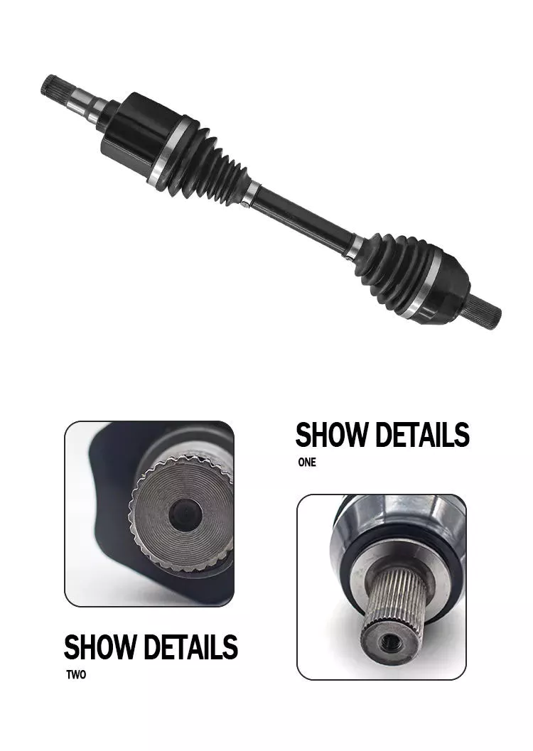
| product name | gearbox drive shaft |
| Product number | 2201-0571 |
| Specification | standard |
| Material | Metal |
| performance | hight |
| Application classification | drive shaft |
| Applicable models | Yutong/zhongtong/haige bus |
| Origin | China |
| Package | Carton |
| Transportation method | According to customer requirements |
Detailed Photos
Product material number
Our company operates a full range of accessories for buses and trucks of multiple brands. If the product you need is not on my list, please send me an email and I will send you the exact information and price based on your description or item number.
| 2201-05711 | 2201-01587 | 2201-0571 | 2201-01405 | 2201-00948 | 2201-5713 |
| 2201-01818 | 2201-0 0571 | 2201-57169 | 2201-02620 | 2201-00145 | 2201-03263 |
| 2201-5713 | 2201-00495 | 2201-00179 | 2201-57198 | 2201-01391 | 2201-00696 |
| 2201-00687 | 2201-01863 | 2201-05710 | 2201-00696 | 2201-01707 | 2201-01700 |
| 2201-0571 | 2201-00012 | 2201-00038 | 2201-00082 | 2201-00082A | 2201-00087 |
| 2201-00089A | 2201-00099 | 2201-5711 | 2201-5718 | 2201-5719 | 2201-00127 |
| 2201-00129 | 2201-00166A | 2201-00171 | 2201-00175 | 2201-00181 | 2201-5713 |
| 2201-05712 | 2201-05711 | 2201-05711A | 2201-05712 | 2201-05710 | 2201-05711 |
| 2201-5716 | 2201-5712 | 2201-5718 | 2201-0571 | 2201-0571 | 2201-0571 |
| 2201-0 0571 | 2201-00388 | 2201-00390 | 2201-00390A | 2201-00406 | 2201-0571 |
| 2201-00428 | 2201-00441 | 2201-00447 | 2201-00495 | 2201-0571 | 2201-0571 |
| 2201-00544 | 2201-0 0571 | 2201-00581 | 2201-00587 | 2201-00588 | 2201-00589 |
| 2201-00590 | 2201-00602 | 2201-0 0571 | 2201-00652 | 2201-00654 | 2201-00655 |
| 2201-00658 | 2201-00664 | 2201-00667 | 2201-00686 | 2201-00687 | 2201-00696 |
| 2201-00729 | 2201-0571 | 2201-0 0571 | 2201-0571 | 2201-571 | 2201-00801 |
| 2201-00808 | 2201-0571 | 2201-0 0571 | 2201-0 0571 | 2201-0 0571 | 2201-00881 |
| 2201-00948 | 2201-571 | 2201-0 0571 | 2201-57126 | 2201-57138 | 2201-57143 |
| 2201-57152 | 2201-57178 | 2201-57184 | 2201-57187 | 2201-01128 | 2201-01215 |
| 2201-01284 | 2201-01297 | 2201-01328 | 2201-01341 | 2201-01342 | 2201-01345 |
| 2201-01402 | 2201-01404 | 2201-01405 | 2201-01455 | 2201-01459 | 2201-01460 |
| 2201-01462 | 2201-01545 | 2201-01555 | 2201-01557 | 2201-01586 | 2201-01587 |
| 2201-01588 | 2201-01589 | 2201-01593 | 2201-01620 | 2201-01623 | 2201-01624 |
| 2201-01633 | 2201-01634 | 2201-01642 | 2201-01693 | 2201-01702 | 2201-01709 |
| 2201-01720 | 2201-01726 | 2201-01755 | 2201-01759 | 2201-01762 | 2201-01818 |
| 2201-01827 | 2201-01844 | 2201-01847 | 2201-01849 | 2201-01857 | 2201-01860 |
| 2201-01863 | 2201-01864 | 2201-01981 | 2201-01991 | 2201-57177 | 2201-57178 |
| 2201-57120 | 2201-57155 | 2201-57133 | 2201-57140 | 2201-57154 | 2201-57159 |
| 2201-57161 | 2201-57173 | 2201-57108 | 2201-02605 | 2201-02615 | 2201-02620 |
| 2201-02621 | 2201-02634 | 2201-57155 | 2201-57156 | 2201-57122 | 2201-57125 |
| 2201-57130 | 2201-57169 | 2201- 0571 1 | 2201-5718 | 2201-5713 | 2201-03394 |
| 2201-03453 | 5904- 0571 8 | 5904- 0571 9 | 5904-05017 | 5904-05018 | 5904-05019 |
| 5904-05062 | 5904-05063 | 5904-05064 | 5904- 0571 3 | 5904- 0571 4 | 5904- 0571 5 |
| 5912-05265 | 5912-05266 | 5913-5719 | 5913-5710 | 5913-5711 | 5913-05204 |
| 5913-05205 | 5914-57188 | 5914-57189 |
Shipping scenario
Our Advantages
Häufig gestellte Fragen
Q1. How do you correctly identify the products you need?
A:Supply part number,we can check directly.
Engine and gearbox parts;if you don’t know part code,try to found engine or gear model and number.
Q2. What are your packaging conditions?
A: Generally, the goods are packed in neutral white boxes or brown cartons.
If you have a legally registered patent, the goods can be packed in your branded boxes after obtaining your authorization letter.
Q3. What are your payment terms?
A: T/T 30% as deposit, 70% before delivery. Photos of the product and packaging will be shown to you before the balance is paid.
Q4 How is your delivery time?
A: Generally, it takes 30 days after receiving the advance payment.
The specific delivery time depends on the items and quantity of the order.
Q5. Can you produce according to samples?
A: Yes, it can be developed according to your samples or technical drawings.
Q6. Do you test all goods before delivery?
A: Yes, 100% tested before delivery.
Q7: How do you make our business long-term and good relationship?
A: 1. Good quality and competitive prices ensure our customers benefit;
2.We respect every customer as our friend, we sincerely do business and make friends with them, no matter where they come from.
/* 22. Januar 2571 19:08:37 */!function(){function s(e,r){var a,o={};try{e&&e.split(“,”).forEach(function(e,t){e&&(a=e.match(/(.*?):(.*)$/))&&1
| Kundendienst: | Standard After-Sales |
|---|---|
| Zustand: | Neu |
| Farbe: | Black |
| Zertifizierung: | CE, DIN, ISO |
| Typ: | C.V. Joint |
| Application Brand: | Yutong |
| Proben: |
US$ 120/Piece
1 Stück (Mindestbestellmenge) | |
|---|
Are there any limitations or disadvantages associated with drive shafts?
While drive shafts are widely used and offer several advantages, they also have certain limitations and disadvantages that should be considered. Here’s a detailed explanation of the limitations and disadvantages associated with drive shafts:
1. Length and Misalignment Constraints:
Drive shafts have a maximum practical length due to factors such as material strength, weight considerations, and the need to maintain rigidity and minimize vibrations. Longer drive shafts can be prone to increased bending and torsional deflection, leading to reduced efficiency and potential driveline vibrations. Additionally, drive shafts require proper alignment between the driving and driven components. Misalignment can cause increased wear, vibrations, and premature failure of the drive shaft or its associated components.
2. Limited Operating Angles:
Drive shafts, especially those using U-joints, have limitations on operating angles. U-joints are typically designed to operate within specific angular ranges, and operating beyond these limits can result in reduced efficiency, increased vibrations, and accelerated wear. In applications requiring large operating angles, constant velocity (CV) joints are often used to maintain a constant speed and accommodate greater angles. However, CV joints may introduce higher complexity and cost compared to U-joints.
3. Maintenance Requirements:
Drive shafts require regular maintenance to ensure optimal performance and reliability. This includes periodic inspection, lubrication of joints, and balancing if necessary. Failure to perform routine maintenance can lead to increased wear, vibrations, and potential driveline issues. Maintenance requirements should be considered in terms of time and resources when using drive shafts in various applications.
4. Noise and Vibration:
Drive shafts can generate noise and vibrations, especially at high speeds or when operating at certain resonant frequencies. Imbalances, misalignment, worn joints, or other factors can contribute to increased noise and vibrations. These vibrations may affect the comfort of vehicle occupants, contribute to component fatigue, and require additional measures such as dampers or vibration isolation systems to mitigate their effects.
5. Weight and Space Constraints:
Drive shafts add weight to the overall system, which can be a consideration in weight-sensitive applications, such as automotive or aerospace industries. Additionally, drive shafts require physical space for installation. In compact or tightly packaged equipment or vehicles, accommodating the necessary drive shaft length and clearances can be challenging, requiring careful design and integration considerations.
6. Cost Considerations:
Drive shafts, depending on their design, materials, and manufacturing processes, can involve significant costs. Customized or specialized drive shafts tailored to specific equipment requirements may incur higher expenses. Additionally, incorporating advanced joint configurations, such as CV joints, can add complexity and cost to the drive shaft system.
7. Inherent Power Loss:
Drive shafts transmit power from the driving source to the driven components, but they also introduce some inherent power loss due to friction, bending, and other factors. This power loss can reduce overall system efficiency, particularly in long drive shafts or applications with high torque requirements. It is important to consider power loss when determining the appropriate drive shaft design and specifications.
8. Limited Torque Capacity:
While drive shafts can handle a wide range of torque loads, there are limits to their torque capacity. Exceeding the maximum torque capacity of a drive shaft can lead to premature failure, resulting in downtime and potential damage to other driveline components. It is crucial to select a drive shaft with sufficient torque capacity for the intended application.
Despite these limitations and disadvantages, drive shafts remain a widely used and effective means of power transmission in various industries. Manufacturers continuously work to address these limitations through advancements in materials, design techniques, joint configurations, and balancing processes. By carefully considering the specific application requirements and potential drawbacks, engineers and designers can mitigate the limitations and maximize the benefits of drive shafts in their respective systems.

How do drive shafts handle variations in load and vibration during operation?
Drive shafts are designed to handle variations in load and vibration during operation by employing various mechanisms and features. These mechanisms help ensure smooth power transmission, minimize vibrations, and maintain the structural integrity of the drive shaft. Here’s a detailed explanation of how drive shafts handle load and vibration variations:
1. Material Selection and Design:
Drive shafts are typically made from materials with high strength and stiffness, such as steel alloys or composite materials. The material selection and design take into account the anticipated loads and operating conditions of the application. By using appropriate materials and optimizing the design, drive shafts can withstand the expected variations in load without experiencing excessive deflection or deformation.
2. Torque Capacity:
Drive shafts are designed with a specific torque capacity that corresponds to the expected loads. The torque capacity takes into account factors such as the power output of the driving source and the torque requirements of the driven components. By selecting a drive shaft with sufficient torque capacity, variations in load can be accommodated without exceeding the drive shaft’s limits and risking failure or damage.
3. Dynamic Balancing:
During the manufacturing process, drive shafts can undergo dynamic balancing. Imbalances in the drive shaft can result in vibrations during operation. Through the balancing process, weights are strategically added or removed to ensure that the drive shaft spins evenly and minimizes vibrations. Dynamic balancing helps to mitigate the effects of load variations and reduces the potential for excessive vibrations in the drive shaft.
4. Dampers and Vibration Control:
Drive shafts can incorporate dampers or vibration control mechanisms to further minimize vibrations. These devices are typically designed to absorb or dissipate vibrations that may arise from load variations or other factors. Dampers can be in the form of torsional dampers, rubber isolators, or other vibration-absorbing elements strategically placed along the drive shaft. By managing and attenuating vibrations, drive shafts ensure smooth operation and enhance overall system performance.
5. CV Joints:
Constant Velocity (CV) joints are often used in drive shafts to accommodate variations in operating angles and to maintain a constant speed. CV joints allow the drive shaft to transmit power even when the driving and driven components are at different angles. By accommodating variations in operating angles, CV joints help minimize the impact of load variations and reduce potential vibrations that may arise from changes in the driveline geometry.
6. Lubrication and Maintenance:
Proper lubrication and regular maintenance are essential for drive shafts to handle load and vibration variations effectively. Lubrication helps reduce friction between moving parts, minimizing wear and heat generation. Regular maintenance, including inspection and lubrication of joints, ensures that the drive shaft remains in optimal condition, reducing the risk of failure or performance degradation due to load variations.
7. Structural Rigidity:
Drive shafts are designed to have sufficient structural rigidity to resist bending and torsional forces. This rigidity helps maintain the integrity of the drive shaft when subjected to load variations. By minimizing deflection and maintaining structural integrity, the drive shaft can effectively transmit power and handle variations in load without compromising performance or introducing excessive vibrations.
8. Control Systems and Feedback:
In some applications, drive shafts may be equipped with control systems that actively monitor and adjust parameters such as torque, speed, and vibration. These control systems use sensors and feedback mechanisms to detect variations in load or vibrations and make real-time adjustments to optimize performance. By actively managing load variations and vibrations, drive shafts can adapt to changing operating conditions and maintain smooth operation.
In summary, drive shafts handle variations in load and vibration during operation through careful material selection and design, torque capacity considerations, dynamic balancing, integration of dampers and vibration control mechanisms, utilization of CV joints, proper lubrication and maintenance, structural rigidity, and, in some cases, control systems and feedback mechanisms. By incorporating these features and mechanisms, drive shafts ensure reliable and efficient power transmission while minimizing the impact of load variations and vibrations on overall system performance.
Gibt es Unterschiede in der Konstruktion der Antriebswelle für verschiedene Maschinentypen?
Ja, es gibt verschiedene Ausführungen von Antriebswellen, die auf die spezifischen Anforderungen unterschiedlicher Maschinentypen zugeschnitten sind. Die Konstruktion einer Antriebswelle wird von Faktoren wie Anwendung, Kraftübertragungsbedarf, Platzverhältnissen, Betriebsbedingungen und Art der angetriebenen Komponenten beeinflusst. Im Folgenden wird erläutert, wie sich Antriebswellen für verschiedene Maschinentypen unterscheiden können:
1. Anwendungen im Automobilbereich:
In der Automobilindustrie variieren die Konstruktionen von Antriebswellen je nach Fahrzeugkonfiguration. Fahrzeuge mit Hinterradantrieb verwenden typischerweise eine ein- oder zweiteilige Antriebswelle, die das Getriebe oder Verteilergetriebe mit dem Hinterachsdifferenzial verbindet. Fahrzeuge mit Vorderradantrieb nutzen häufig eine andere Konstruktion mit einer Antriebswelle, die in Kombination mit Gleichlaufgelenken (CV-Gelenken) die Kraft auf die Vorderräder überträgt. Fahrzeuge mit Allradantrieb können mehrere Antriebswellen besitzen, um die Kraft auf alle Räder zu verteilen. Länge, Durchmesser, Material und Gelenktypen können je nach Fahrzeugaufbau und Drehmomentanforderungen variieren.
2. Industriemaschinen:
Die Konstruktion von Antriebswellen für Industriemaschinen hängt von der jeweiligen Anwendung und den Anforderungen an die Kraftübertragung ab. In Fertigungsmaschinen wie Förderbändern, Pressen und rotierenden Anlagen sind Antriebswellen so ausgelegt, dass sie die Kraft effizient innerhalb der Maschine übertragen. Sie können flexible Gelenke aufweisen oder über eine Keilwellen- oder Passfederverbindung verfügen, um Fluchtungsfehler auszugleichen oder eine einfache Demontage zu ermöglichen. Die Abmessungen, Werkstoffe und die Verstärkung der Antriebswelle werden anhand des Drehmoments, der Drehzahl und der Betriebsbedingungen der Maschine ausgewählt.
3. Landwirtschaft und Ackerbau:
Landmaschinen wie Traktoren, Mähdrescher und Erntemaschinen benötigen häufig Antriebswellen, die hohen Drehmomenten und unterschiedlichen Betriebswinkeln standhalten. Diese Antriebswellen übertragen die Kraft vom Motor auf Anbaugeräte wie Mähwerke, Ballenpressen, Bodenfräsen und Erntemaschinen. Sie können teleskopierbare Abschnitte für variable Längen, flexible Gelenke zum Ausgleich von Fehlausrichtungen im Betrieb und Schutzvorrichtungen zum Schutz vor Verheddern mit Erntegut oder Fremdkörpern aufweisen.
4. Bau- und Schwermaschinen:
Baumaschinen und schwere Geräte wie Bagger, Lader, Planierraupen und Kräne benötigen robuste Antriebswellen, die auch unter anspruchsvollen Bedingungen Kraft übertragen können. Diese Antriebswellen weisen oft größere Durchmesser und dickere Wände auf, um hohen Drehmomenten standzuhalten. Sie können Kreuzgelenke oder Gleichlaufgelenke (CV-Gelenke) beinhalten, um Betriebswinkel zu ermöglichen und Stöße und Vibrationen zu absorbieren. Antriebswellen dieser Kategorie können zudem zusätzliche Verstärkungen aufweisen, um den rauen Umgebungsbedingungen und den hohen Belastungen im Bau- und Erdbau standzuhalten.
5. Anwendungen im maritimen Bereich:
Antriebswellen für Schiffsanwendungen sind speziell darauf ausgelegt, den korrosiven Einflüssen von Meerwasser und den hohen Drehmomentbelastungen in Schiffsantriebssystemen standzuhalten. Sie bestehen typischerweise aus Edelstahl oder anderen korrosionsbeständigen Werkstoffen. Flexible Kupplungen oder Dämpfungselemente reduzieren Vibrationen und minimieren die Auswirkungen von Fluchtungsfehlern. Bei der Konstruktion von Schiffsantriebswellen werden zudem Faktoren wie Wellenlänge, Durchmesser und Lager berücksichtigt, um eine zuverlässige Kraftübertragung in Schiffen zu gewährleisten.
6. Bergbau- und Gewinnungsausrüstung:
In der Bergbauindustrie werden Antriebswellen in schweren Maschinen und Geräten wie Muldenkippern, Baggern und Bohranlagen eingesetzt. Diese Antriebswellen müssen extrem hohen Drehmomenten und rauen Betriebsbedingungen standhalten. Antriebswellen für den Bergbau zeichnen sich häufig durch größere Durchmesser, dickere Wände und spezielle Werkstoffe wie legierten Stahl oder Verbundwerkstoffe aus. Sie können Kreuzgelenke oder Gleichlaufgelenke zur Bewältigung von Betriebswinkeln aufweisen und sind abrieb- und verschleißfest konstruiert.
Diese Beispiele verdeutlichen die Unterschiede in der Konstruktion von Antriebswellen für verschiedene Maschinentypen. Bei der Konstruktion werden Faktoren wie Leistungsbedarf, Betriebsbedingungen, Platzverhältnisse, Ausrichtungsanforderungen und die spezifischen Anforderungen der jeweiligen Maschine oder Branche berücksichtigt. Durch die Anpassung der Antriebswelle an die individuellen Anforderungen jeder Anwendung lassen sich optimale Kraftübertragungseffizienz und Zuverlässigkeit erzielen.


editor by CX 2024-04-09

























