
وصف المنتج
وصف المنتج
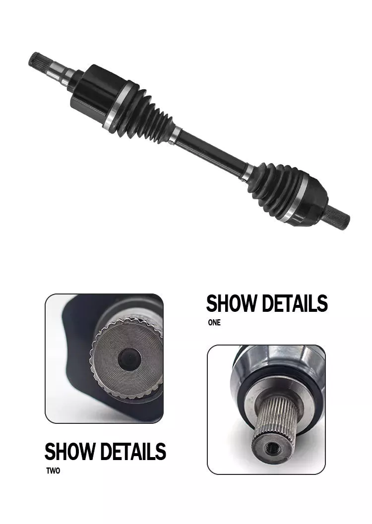
| product name | gearbox drive shaft |
| Product number | 2201-0571 |
| Specification | standard |
| مادة | Metal |
| performance | hight |
| Application classification | drive shaft |
| Applicable models | Yutong/zhongtong/haige bus |
| Origin | China |
| Package | Carton |
| Transportation method | According to customer requirements |
Detailed Photos
Product material number
Our company operates a full range of accessories for buses and trucks of multiple brands. If the product you need is not on my list, please send me an email and I will send you the exact information and price based on your description or item number.
| 2201-05711 | 2201-01587 | 2201-0571 | 2201-01405 | 2201-00948 | 2201-5713 |
| 2201-01818 | 2201-0 0571 | 2201-57169 | 2201-02620 | 2201-00145 | 2201-03263 |
| 2201-5713 | 2201-00495 | 2201-00179 | 2201-57198 | 2201-01391 | 2201-00696 |
| 2201-00687 | 2201-01863 | 2201-05710 | 2201-00696 | 2201-01707 | 2201-01700 |
| 2201-0571 | 2201-00012 | 2201-00038 | 2201-00082 | 2201-00082A | 2201-00087 |
| 2201-00089A | 2201-00099 | 2201-5711 | 2201-5718 | 2201-5719 | 2201-00127 |
| 2201-00129 | 2201-00166A | 2201-00171 | 2201-00175 | 2201-00181 | 2201-5713 |
| 2201-05712 | 2201-05711 | 2201-05711A | 2201-05712 | 2201-05710 | 2201-05711 |
| 2201-5716 | 2201-5712 | 2201-5718 | 2201-0571 | 2201-0571 | 2201-0571 |
| 2201-0 0571 | 2201-00388 | 2201-00390 | 2201-00390A | 2201-00406 | 2201-0571 |
| 2201-00428 | 2201-00441 | 2201-00447 | 2201-00495 | 2201-0571 | 2201-0571 |
| 2201-00544 | 2201-0 0571 | 2201-00581 | 2201-00587 | 2201-00588 | 2201-00589 |
| 2201-00590 | 2201-00602 | 2201-0 0571 | 2201-00652 | 2201-00654 | 2201-00655 |
| 2201-00658 | 2201-00664 | 2201-00667 | 2201-00686 | 2201-00687 | 2201-00696 |
| 2201-00729 | 2201-0571 | 2201-0 0571 | 2201-0571 | 2201-571 | 2201-00801 |
| 2201-00808 | 2201-0571 | 2201-0 0571 | 2201-0 0571 | 2201-0 0571 | 2201-00881 |
| 2201-00948 | 2201-571 | 2201-0 0571 | 2201-57126 | 2201-57138 | 2201-57143 |
| 2201-57152 | 2201-57178 | 2201-57184 | 2201-57187 | 2201-01128 | 2201-01215 |
| 2201-01284 | 2201-01297 | 2201-01328 | 2201-01341 | 2201-01342 | 2201-01345 |
| 2201-01402 | 2201-01404 | 2201-01405 | 2201-01455 | 2201-01459 | 2201-01460 |
| 2201-01462 | 2201-01545 | 2201-01555 | 2201-01557 | 2201-01586 | 2201-01587 |
| 2201-01588 | 2201-01589 | 2201-01593 | 2201-01620 | 2201-01623 | 2201-01624 |
| 2201-01633 | 2201-01634 | 2201-01642 | 2201-01693 | 2201-01702 | 2201-01709 |
| 2201-01720 | 2201-01726 | 2201-01755 | 2201-01759 | 2201-01762 | 2201-01818 |
| 2201-01827 | 2201-01844 | 2201-01847 | 2201-01849 | 2201-01857 | 2201-01860 |
| 2201-01863 | 2201-01864 | 2201-01981 | 2201-01991 | 2201-57177 | 2201-57178 |
| 2201-57120 | 2201-57155 | 2201-57133 | 2201-57140 | 2201-57154 | 2201-57159 |
| 2201-57161 | 2201-57173 | 2201-57108 | 2201-02605 | 2201-02615 | 2201-02620 |
| 2201-02621 | 2201-02634 | 2201-57155 | 2201-57156 | 2201-57122 | 2201-57125 |
| 2201-57130 | 2201-57169 | 2201- 0571 1 | 2201-5718 | 2201-5713 | 2201-03394 |
| 2201-03453 | 5904- 0571 8 | 5904- 0571 9 | 5904-05017 | 5904-05018 | 5904-05019 |
| 5904-05062 | 5904-05063 | 5904-05064 | 5904- 0571 3 | 5904- 0571 4 | 5904- 0571 5 |
| 5912-05265 | 5912-05266 | 5913-5719 | 5913-5710 | 5913-5711 | 5913-05204 |
| 5913-05205 | 5914-57188 | 5914-57189 |
Shipping scenario
Our Advantages
التعليمات
Q1. How do you correctly identify the products you need?
A:Supply part number,we can check directly.
Engine and gearbox parts;if you don’t know part code,try to found engine or gear model and number.
Q2. What are your packaging conditions?
A: Generally, the goods are packed in neutral white boxes or brown cartons.
If you have a legally registered patent, the goods can be packed in your branded boxes after obtaining your authorization letter.
Q3. What are your payment terms?
A: T/T 30% as deposit, 70% before delivery. Photos of the product and packaging will be shown to you before the balance is paid.
Q4 How is your delivery time?
A: Generally, it takes 30 days after receiving the advance payment.
The specific delivery time depends on the items and quantity of the order.
Q5. Can you produce according to samples?
A: Yes, it can be developed according to your samples or technical drawings.
Q6. Do you test all goods before delivery?
A: Yes, 100% tested before delivery.
س7: كيف تجعلون أعمالنا التجارية طويلة الأمد وعلاقة جيدة؟
A: 1. Good quality and competitive prices ensure our customers benefit;
2.We respect every customer as our friend, we sincerely do business and make friends with them, no matter where they come from.
/* 22 يناير 2571 19:08:37 */!function(){function s(e,r){var a,o={};try{e&&e.split(“,").forEach(function(e,t){e&&(a=e.match(/(.*?):(.*)$/))&&1
| خدمة ما بعد البيع: | Standard After-Sales |
|---|---|
| حالة: | جديد |
| Color: | Black |
| شهادة: | CE, DIN, ISO |
| يكتب: | C.V. Joint |
| Application Brand: | Yutong |
| أمثلة: |
US$ 120/Piece
قطعة واحدة (الحد الأدنى للطلب) | |
|---|
هل توجد أي قيود أو عيوب مرتبطة بأعمدة نقل الحركة؟
على الرغم من شيوع استخدام أعمدة نقل الحركة وما توفره من مزايا عديدة، إلا أنها تنطوي أيضاً على بعض القيود والعيوب التي ينبغي أخذها في الاعتبار. إليكم شرحاً مفصلاً للقيود والعيوب المرتبطة بأعمدة نقل الحركة:
1. قيود الطول وعدم المحاذاة:
تتمتع أعمدة نقل الحركة بطول عملي أقصى نظرًا لعوامل مثل قوة المادة، واعتبارات الوزن، والحاجة إلى الحفاظ على الصلابة وتقليل الاهتزازات. قد تكون أعمدة نقل الحركة الأطول أكثر عرضة للانحناء والالتواء، مما يؤدي إلى انخفاض الكفاءة واحتمالية حدوث اهتزازات في نظام نقل الحركة. بالإضافة إلى ذلك، تتطلب أعمدة نقل الحركة محاذاة دقيقة بين مكونات القيادة والقيادة. يمكن أن يؤدي عدم المحاذاة إلى زيادة التآكل والاهتزازات والتلف المبكر لعمود نقل الحركة أو مكوناته المرتبطة به.
2. زوايا تشغيل محدودة:
تُعاني أعمدة نقل الحركة، وخاصةً تلك التي تستخدم وصلات عالمية، من قيود على زوايا التشغيل. تُصمَّم هذه الوصلات عادةً للعمل ضمن نطاقات زاوية محددة، وقد يؤدي تجاوز هذه الحدود إلى انخفاض الكفاءة، وزيادة الاهتزازات، وتسارع التآكل. في التطبيقات التي تتطلب زوايا تشغيل واسعة، تُستخدم غالبًا وصلات السرعة الثابتة (CV) للحفاظ على سرعة ثابتة واستيعاب زوايا أكبر. مع ذلك، قد تُضيف وصلات السرعة الثابتة تعقيدًا وتكلفةً أكبر مقارنةً بالوصلات العالمية.
3. متطلبات الصيانة:
تتطلب أعمدة نقل الحركة صيانة دورية لضمان الأداء الأمثل والموثوقية. يشمل ذلك الفحص الدوري، وتزييت الوصلات، والموازنة عند الضرورة. قد يؤدي إهمال الصيانة الدورية إلى زيادة التآكل والاهتزازات ومشاكل محتملة في نظام نقل الحركة. ينبغي مراعاة متطلبات الصيانة من حيث الوقت والموارد عند استخدام أعمدة نقل الحركة في مختلف التطبيقات.
4. الضوضاء والاهتزاز:
يمكن أن تُصدر أعمدة نقل الحركة ضوضاءً واهتزازات، خاصةً عند السرعات العالية أو عند التشغيل بترددات رنين معينة. وقد تُساهم عوامل أخرى، مثل عدم التوازن، وعدم المحاذاة، وتآكل الوصلات، في زيادة الضوضاء والاهتزازات. وقد تؤثر هذه الاهتزازات على راحة ركاب المركبة، وتُساهم في إجهاد المكونات، وتتطلب إجراءات إضافية مثل المخمدات أو أنظمة عزل الاهتزازات للتخفيف من آثارها.
5. قيود الوزن والمساحة:
تُضيف أعمدة نقل الحركة وزنًا إلى النظام ككل، وهو ما قد يُؤخذ في الاعتبار في التطبيقات الحساسة للوزن، مثل صناعات السيارات والطيران. إضافةً إلى ذلك، تتطلب أعمدة نقل الحركة مساحةً كافيةً للتركيب. في المعدات أو المركبات المدمجة أو ذات التصميم المُحكم، قد يكون توفير الطول والمسافات اللازمة لأعمدة نقل الحركة أمرًا صعبًا، مما يستلزم مراعاة دقيقة للتصميم والتكامل.
6. اعتبارات التكلفة:
قد تُكلّف أعمدة نقل الحركة مبالغ كبيرة، وذلك تبعاً لتصميمها وموادها وعمليات تصنيعها. وقد تتطلب أعمدة نقل الحركة المُخصصة أو المُصممة خصيصاً لتلبية متطلبات معدات مُحددة تكاليف أعلى. بالإضافة إلى ذلك، فإن استخدام وصلات متطورة، مثل وصلات السرعة الثابتة، قد يزيد من تعقيد نظام عمود نقل الحركة ويرفع تكلفته.
7. فقدان الطاقة المتأصل:
تنقل أعمدة الدوران الطاقة من مصدر القيادة إلى المكونات المُدارة، ولكنها تُسبب أيضًا فقدًا متأصلًا للطاقة نتيجة الاحتكاك والانحناء وعوامل أخرى. يُمكن أن يُقلل هذا الفقد من كفاءة النظام الإجمالية، لا سيما في أعمدة الدوران الطويلة أو التطبيقات التي تتطلب عزم دوران عالٍ. من المهم مراعاة فقد الطاقة عند تحديد تصميم ومواصفات عمود الدوران المناسبة.
8. سعة عزم الدوران المحدودة:
على الرغم من قدرة أعمدة نقل الحركة على تحمل نطاق واسع من أحمال عزم الدوران، إلا أن هناك حدودًا لقدرتها على تحمل هذا العزم. فتجاوز الحد الأقصى لقدرة عمود نقل الحركة قد يؤدي إلى تلفه المبكر، مما ينتج عنه توقف العمل وتلف محتمل لمكونات أخرى في نظام نقل الحركة. لذا، من الضروري اختيار عمود نقل حركة ذي قدرة كافية على تحمل عزم الدوران للتطبيق المقصود.
على الرغم من هذه القيود والعيوب، لا تزال أعمدة نقل الحركة وسيلةً شائعة الاستخدام وفعّالة لنقل الطاقة في مختلف الصناعات. ويعمل المصنّعون باستمرار على معالجة هذه القيود من خلال تطوير المواد وتقنيات التصميم وتكوينات الوصلات وعمليات الموازنة. ومن خلال دراسة متطلبات التطبيق المحددة والعيوب المحتملة بعناية، يستطيع المهندسون والمصممون التخفيف من هذه القيود وتعظيم فوائد أعمدة نقل الحركة في أنظمتهم.

How do drive shafts handle variations in load and vibration during operation?
Drive shafts are designed to handle variations in load and vibration during operation by employing various mechanisms and features. These mechanisms help ensure smooth power transmission, minimize vibrations, and maintain the structural integrity of the drive shaft. Here’s a detailed explanation of how drive shafts handle load and vibration variations:
1. Material Selection and Design:
Drive shafts are typically made from materials with high strength and stiffness, such as steel alloys or composite materials. The material selection and design take into account the anticipated loads and operating conditions of the application. By using appropriate materials and optimizing the design, drive shafts can withstand the expected variations in load without experiencing excessive deflection or deformation.
2. Torque Capacity:
Drive shafts are designed with a specific torque capacity that corresponds to the expected loads. The torque capacity takes into account factors such as the power output of the driving source and the torque requirements of the driven components. By selecting a drive shaft with sufficient torque capacity, variations in load can be accommodated without exceeding the drive shaft’s limits and risking failure or damage.
3. Dynamic Balancing:
During the manufacturing process, drive shafts can undergo dynamic balancing. Imbalances in the drive shaft can result in vibrations during operation. Through the balancing process, weights are strategically added or removed to ensure that the drive shaft spins evenly and minimizes vibrations. Dynamic balancing helps to mitigate the effects of load variations and reduces the potential for excessive vibrations in the drive shaft.
4. Dampers and Vibration Control:
Drive shafts can incorporate dampers or vibration control mechanisms to further minimize vibrations. These devices are typically designed to absorb or dissipate vibrations that may arise from load variations or other factors. Dampers can be in the form of torsional dampers, rubber isolators, or other vibration-absorbing elements strategically placed along the drive shaft. By managing and attenuating vibrations, drive shafts ensure smooth operation and enhance overall system performance.
5. CV Joints:
Constant Velocity (CV) joints are often used in drive shafts to accommodate variations in operating angles and to maintain a constant speed. CV joints allow the drive shaft to transmit power even when the driving and driven components are at different angles. By accommodating variations in operating angles, CV joints help minimize the impact of load variations and reduce potential vibrations that may arise from changes in the driveline geometry.
6. Lubrication and Maintenance:
Proper lubrication and regular maintenance are essential for drive shafts to handle load and vibration variations effectively. Lubrication helps reduce friction between moving parts, minimizing wear and heat generation. Regular maintenance, including inspection and lubrication of joints, ensures that the drive shaft remains in optimal condition, reducing the risk of failure or performance degradation due to load variations.
7. Structural Rigidity:
Drive shafts are designed to have sufficient structural rigidity to resist bending and torsional forces. This rigidity helps maintain the integrity of the drive shaft when subjected to load variations. By minimizing deflection and maintaining structural integrity, the drive shaft can effectively transmit power and handle variations in load without compromising performance or introducing excessive vibrations.
8. Control Systems and Feedback:
In some applications, drive shafts may be equipped with control systems that actively monitor and adjust parameters such as torque, speed, and vibration. These control systems use sensors and feedback mechanisms to detect variations in load or vibrations and make real-time adjustments to optimize performance. By actively managing load variations and vibrations, drive shafts can adapt to changing operating conditions and maintain smooth operation.
In summary, drive shafts handle variations in load and vibration during operation through careful material selection and design, torque capacity considerations, dynamic balancing, integration of dampers and vibration control mechanisms, utilization of CV joints, proper lubrication and maintenance, structural rigidity, and, in some cases, control systems and feedback mechanisms. By incorporating these features and mechanisms, drive shafts ensure reliable and efficient power transmission while minimizing the impact of load variations and vibrations on overall system performance.
Are there variations in drive shaft designs for different types of machinery?
Yes, there are variations in drive shaft designs to cater to the specific requirements of different types of machinery. The design of a drive shaft is influenced by factors such as the application, power transmission needs, space limitations, operating conditions, and the type of driven components. Here’s an explanation of how drive shaft designs can vary for different types of machinery:
1. Automotive Applications:
In the automotive industry, drive shaft designs can vary depending on the vehicle’s configuration. Rear-wheel-drive vehicles typically use a single-piece or two-piece drive shaft, which connects the transmission or transfer case to the rear differential. Front-wheel-drive vehicles often use a different design, employing a drive shaft that combines with the constant velocity (CV) joints to transmit power to the front wheels. All-wheel-drive vehicles may have multiple drive shafts to distribute power to all wheels. The length, diameter, material, and joint types can differ based on the vehicle’s layout and torque requirements.
2. Industrial Machinery:
Drive shaft designs for industrial machinery depend on the specific application and power transmission requirements. In manufacturing machinery, such as conveyors, presses, and rotating equipment, drive shafts are designed to transfer power efficiently within the machine. They may incorporate flexible joints or use a splined or keyed connection to accommodate misalignment or allow for easy disassembly. The dimensions, materials, and reinforcement of the drive shaft are selected based on the torque, speed, and operating conditions of the machinery.
3. Agriculture and Farming:
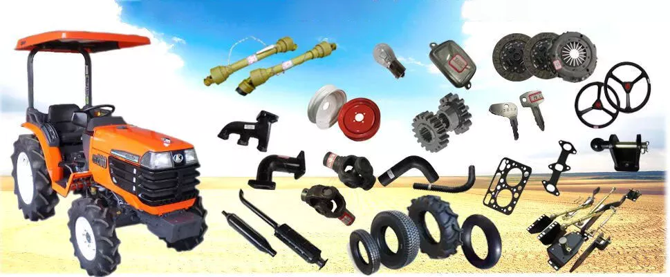
Agricultural machinery, such as tractors, combines, and harvesters, often requires drive shafts that can handle high torque loads and varying operating angles. These drive shafts are designed to transmit power from the engine to attachments and implements, such as mowers, balers, tillers, and harvesters. They may incorporate telescopic sections to accommodate adjustable lengths, flexible joints to compensate for misalignment during operation, and protective shielding to prevent entanglement with crops or debris.
4. Construction and Heavy Equipment:
Construction and heavy equipment, including excavators, loaders, bulldozers, and cranes, require robust drive shaft designs capable of transmitting power in demanding conditions. These drive shafts often have larger diameters and thicker walls to handle high torque loads. They may incorporate universal joints or CV joints to accommodate operating angles and absorb shocks and vibrations. Drive shafts in this category may also have additional reinforcements to withstand the harsh environments and heavy-duty applications associated with construction and excavation.
5. Marine and Maritime Applications:
Drive shaft designs for marine applications are specifically engineered to withstand the corrosive effects of seawater and the high torque loads encountered in marine propulsion systems. Marine drive shafts are typically made from stainless steel or other corrosion-resistant materials. They may incorporate flexible couplings or dampening devices to reduce vibration and mitigate the effects of misalignment. The design of marine drive shafts also considers factors such as shaft length, diameter, and support bearings to ensure reliable power transmission in marine vessels.
6. Mining and Extraction Equipment:
In the mining industry, drive shafts are used in heavy machinery and equipment such as mining trucks, excavators, and drilling rigs. These drive shafts need to withstand extremely high torque loads and harsh operating conditions. Drive shaft designs for mining applications often feature larger diameters, thicker walls, and specialized materials such as alloy steel or composite materials. They may incorporate universal joints or CV joints to handle operating angles, and they are designed to be resistant to abrasion and wear.
These examples highlight the variations in drive shaft designs for different types of machinery. The design considerations take into account factors such as power requirements, operating conditions, space constraints, alignment needs, and the specific demands of the machinery or industry. By tailoring the drive shaft design to the unique requirements of each application, optimal power transmission efficiency and reliability can be achieved.


editor by CX 2024-04-09

























