
Опис продукту
Опис продукту
Warranty
1 рік
Applicable Industries
Hotels, Garment Shops, Building Material Shops, Manufacturing Plant, Machinery Repair Shops, Food & Beverage Factory, Farms, Restaurant, Home Use, Retail, Food Shop, Printing Shops, Construction works , Energy & Mining, Food & Beverage Shops, Other, Advertising Company
Weight (KG)
1
Showroom Location
Viet Nam
Video outgoing-inspection
Provided
Machinery Test Report
Provided
Marketing Type
Ordinary Product
Warranty of core components
1 рік
Core Components
PLC, Engine, Bearing, Gearbox, Motor, Pressure vessel, Gear, Pump
Матеріал
steel
Place of CHINAMFG
ZheJiang , China
Хвороба
Новий
Structure
Вал
Coatings
Налаштовані
Torque Capacity
Налаштовані
Номер моделі
Налаштовані
Назва бренду
NON
Description
Вал
Machining equipment
CNC mill,lathe and grind machine
Матеріал
stainless steel, aluminium, carbon
Surface
Grinding and polishing
Shape
Налаштовані
Sampling time
10days
Production time
20days
Packing
Protective packing
Tolerance
±0.001
OEM
Welcome
Production Process
Профіль компанії
HangZhou HUANENGDA SPRING CO.,LTD
HangZhou HuaNengDa Spring Co., Ltd. is located in Tong ‘an District, HangZhou City, ZheJiang Province, China. It is a hardware factory specializing in R&D design, manufacture and sales of precision components. The company introduces domestic and foreign advanced equipment and production technology, adopts CNC high-precision computer machine, compression spring machine, CNC five-axis linkage machining center, CNC turning and milling compound, 300 tons of punch and other mechanical equipment,and employs senior engineers with more than 10 years of work experience to debug mechanical equipment and customize production.
With the business philosophy of honesty, pragmatism and excellence, HuaNengDa Spring Company is dedicated to serving customers at home and abroad. We hope that the products of HuaNengDa will help your business to be more brilliant, let us build a bright future in the high-tech era!
The testimony is pragmatic and the attitude of the people. Quality service is the pursuit of the people!
Factory Workshop
Production Procedur
Quality Inspection
Packing And Shipping
Our Service
Найчастіші запитання
1.Small order quantity is workable
From the initial sample design of the spring to the mass production of the springs, we can quickly reach your manufacturing goals and immediately provide the best products because we have an excellent production management system and expertly trained technical personnel.
2.Committed to high quality production
To keep HuaNengDa Springs at the forefront of the industry, we have implemented a stringent internal quality control system and regularly import the latest manufacturing equipment and instruments. Through our precise manufacturing technology and expert mold making process, we provide our customers with the best products and service.
3.Efficiency in manufacturing
Our company’s machinery and equipment are controlled by CNC computers. In order to respond to international needs and standards, we continuously update and upgrade our equipment every year. Our machines effectively increase production capacity and save on manufacturing costs. The manufacturing department is the most important core of the whole company and by treating it with utmost importance, we reap great benefits in manufacturing efficiency.
4.Excellent customization services
HuaNengDa’s R&D team designs and completes customized products according to the needs of customers. From the selection of materials to the function of the products, we can design and develop products to suite different customers’ requirements. We are constantly involving ourselves in all aspects of the industry because only by having a complete view and analysis of the industry, can there be innovative breakthroughs.
Payment term
*T/T : 30% pre T/T, 70% before delivery.
*Trade Assurance
Service
*Delivery on time.
*Shipped by a convenient and cost-effective way.
*Good after-selling, 24 hours service for you.
Packing
*A: Poly bag, Plstic tray ,small box, carton.
*B: According to customers’ requirements.
Delivery
*Sample: 7-10 days after deposit received.
*Batch goods: 12-15 days after samples approved. /* January 22, 2571 19:08:37 */!function(){function s(e,r){var a,o={};try{e&&e.split(“,”).forEach(function(e,t){e&&(a=e.match(/(.*?):(.*)$/))&&1
| Хвороба: | Новий |
|---|---|
| Сертифікація: | ISO9001 |
| Стандарт: | DIN, ASTM, ГОСТ, GB, JIS, ANSI, BS |
| Налаштовано: | Налаштовані |
| Матеріал: | Steel,Stainless Steel,Iron |
| Застосування: | Metal Processing Machinery Parts |
| Зразки: |
US$ 10/Piece
1 штука (мінімальне замовлення) | |
|---|
| Налаштування: |
Доступно
| Індивідуальний запит |
|---|

Як вали відбору потужності справляються з різною довжиною та способами підключення?
Вали відбору потужності (ВОМ) розроблені з урахуванням різної довжини та способів підключення, щоб адаптуватися до різних конфігурацій обладнання та забезпечити ефективну передачу потужності. Вали ВОМ повинні мати регульовану довжину, щоб зменшити відстань між джерелом живлення та приводним механізмом. Крім того, вони повинні забезпечувати універсальні способи підключення до широкого спектру обладнання. Ось детальне пояснення того, як вали ВОМ справляються з різною довжиною та способами підключення:
1. Телескопічна конструкція: Вали відбору потужності часто мають телескопічну конструкцію, що дозволяє регулювати їх довжину відповідно до різних конфігурацій обладнання. Телескопічна функція дозволяє валу висуватися або втягуватися, адаптуючись до різних відстаней між джерелом живлення (наприклад, трактором або двигуном) та керованою машиною. Регулюючи довжину валу відбору потужності, його можна правильно вирівняти та з'єднати для забезпечення оптимальної передачі потужності. Телескопічні вали відбору потужності зазвичай складаються з кількох трубчастих секцій, які ковзають одна в одну, забезпечуючи гнучкість у регулюванні довжини.
2. Шліцьові вали: У валах відбору потужності зазвичай використовуються шліцьові вали як основний метод з'єднання між джерелом живлення та приводним обладнанням. Шліці - це серія виступів або канавок вздовж вала, які зчіплюються з відповідними канавками в сполучному компоненті. Шлицьове з'єднання дозволяє передавати крутний момент, зберігаючи при цьому вирівнювання між джерелом живлення та приводним обладнанням. Шлицьові вали можуть витримувати зміни довжини шляхом висування або втягування телескопічних секцій, зберігаючи при цьому міцне з'єднання між джерелом живлення та приводним обладнанням.
3. Регульовані розсувні хомути: Вали відбору потужності зазвичай мають регульовані ковзні вилки на одному або обох кінцях вала. Ці вилки дозволяють регулювати кут, враховуючи зміни в вирівнюванні між джерелом живлення та приводним механізмом. Ковзні вилки можна переміщувати вздовж шліцьового вала для досягнення потрібного кута та підтримки належного вирівнювання. Ця гнучкість гарантує, що вал відбору потужності може справлятися з змінами довжини, забезпечуючи ефективну передачу потужності без надмірного навантаження на універсальні шарніри або інші компоненти.
4. Універсальні шарніри: Карданні шарніри є невід'ємними компонентами валів відбору потужності, які дозволяють компенсувати кутове зміщення між джерелом живлення та приводним механізмом. Вони складаються з хрестоподібної вилки з підшипниками, які передають крутний момент між з'єднаними валами, одночасно компенсуючи зміщення. Карданні шарніри забезпечують гнучкість у з'єднанні валів відбору потужності з обладнанням, яке може бути не ідеально вирівняне. Оскільки довжина валу відбору потужності змінюється, карданні шарніри компенсують зміни кута, забезпечуючи плавну передачу потужності навіть за наявності варіацій довжини або зміщення між джерелом живлення та приводним механізмом.
5. Механізми зчеплення: Вали відбору потужності використовують різні механізми з'єднання для надійного з'єднання з джерелом живлення та приводним механізмом. Ці механізми часто включають комбінацію шліців, болтів, стопорних штифтів або механізмів швидкого з'єднання. Методи з'єднання можуть відрізнятися залежно від конкретного обладнання та вимог галузі. Універсальність валів відбору потужності дозволяє використовувати різні методи з'єднання, забезпечуючи надійне та безпечне з'єднання незалежно від довжини або конфігурації обладнання.
6. Варіанти налаштування: Вали відбору потужності можна налаштувати для роботи з певними варіаціями довжини та способами з'єднання. Виробники пропонують варіанти вибору телескопічних секцій різної довжини, щоб вони відповідали конкретній відстані між джерелом живлення та приводним механізмом. Крім того, вали відбору потужності можна налаштувати для різних способів з'єднання шляхом вибору розмірів шліцьових валів, конструкцій вилок та механізмів з'єднання. Така налаштування дозволяє валам відбору потужності відповідати конкретним вимогам різних конфігурацій обладнання, забезпечуючи оптимальну передачу потужності та сумісність.
7. Міркування безпеки: Під час роботи з різними типами довжини та способами підключення важливо враховувати безпеку. Вали відбору потужності оснащені захисними кожухами та екранами для запобігання випадковому контакту з обертовими компонентами. Ці заходи безпеки повинні бути належним чином налаштовані та встановлені, щоб забезпечити належне покриття та захист, незалежно від довжини вала відбору потужності або конфігурації з'єднання. Слід дотримуватися правил безпеки, щоб забезпечити правильне встановлення, регулювання та використання валів відбору потужності з метою запобігання нещасним випадкам або травмам.
Завдяки телескопічним конструкціям, шліцьовим валам, регульованим розсувним вилкам, універсальним шарнірам та універсальним механізмам з'єднання, карданні вали можуть працювати з різними типами довжини та способами з'єднання. Гнучкість карданних валів дозволяє їм адаптуватися до різних конфігурацій обладнання, забезпечуючи ефективну передачу потужності, зберігаючи при цьому вирівнювання та безпеку.

How do PTO shafts handle variations in load and torque during operation?
PTO (Power Take-Off) shafts are designed to handle variations in load and torque during operation by employing specific mechanisms and features that ensure efficient power transfer and protection against overload conditions. Here’s a detailed explanation of how PTO shafts handle variations in load and torque:
1. Mechanical Design: PTO shafts are engineered with robust mechanical design principles that enable them to handle variations in load and torque. They are typically constructed using high-strength materials such as steel, which provides durability and resistance to bending or twisting forces. The shaft’s diameter, wall thickness, and overall dimensions are carefully calculated to withstand the expected torque levels and load variations. The mechanical design of the PTO shaft ensures that it can transmit power reliably and accommodate the dynamic forces encountered during operation.
2. Universal Joints: Universal joints are a key component of PTO shafts that allow for flexibility and compensation of misalignment between the power source and driven machinery. These joints can accommodate variations in angular alignment, which may occur due to changes in load or movement of the machinery. Universal joints consist of a cross-shaped yoke with needle bearings that allow for smooth rotation and transfer of torque, even when the shafts are not perfectly aligned. The design of universal joints enables PTO shafts to handle variations in load and torque while maintaining consistent power transmission.
3. Ковзні зчеплення: Slip clutches are often incorporated into PTO shafts to provide overload protection. These clutches allow the PTO shaft to slip or disengage momentarily when excessive torque or resistance is encountered. Slip clutches typically consist of friction plates that can be adjusted to a specific torque setting. When the torque surpasses the predetermined limit, the clutch slips, preventing damage to the PTO shaft and connected equipment. Slip clutches are particularly useful when sudden changes in load or torque occur, providing a safety mechanism to protect the PTO shaft and associated machinery.
4. Torque Limiters: Torque limiters are another protective feature found in some PTO shafts. These devices are designed to automatically disengage the power transmission when a predetermined torque threshold is exceeded. Torque limiters can be mechanical, such as shear pin couplings or friction clutches, or electronic, utilizing sensors and control systems. When the torque exceeds the set limit, the torque limiter disengages, preventing further power transfer and protecting the PTO shaft from overload conditions. Torque limiters are effective in handling sudden spikes in torque and safeguarding the PTO shaft and associated equipment.
5. Технічне обслуговування та перевірка: Regular maintenance and inspection of PTO shafts are essential to ensure their proper functioning and ability to handle variations in load and torque. Routine maintenance includes lubrication of universal joints, inspection of shaft integrity, and tightening of fasteners. Regular inspections allow for early detection of wear, misalignment, or other issues that may affect the PTO shaft’s performance. By addressing maintenance and inspection requirements, operators can identify and address any concerns that may arise due to variations in load and torque, ensuring the continued safe and efficient operation of the PTO shaft.
6. Operator Awareness and Control: Operators play a crucial role in managing variations in load and torque during PTO shaft operation. They should be aware of the machinery’s operational limits, including the recommended torque ratings and load capacities of the PTO shaft. Proper training and understanding of the equipment’s capabilities enable operators to make informed decisions and adjust the operation when encountering significant load or torque changes. Operators should also be vigilant in monitoring the equipment’s performance, watching for any signs of excessive vibration, noise, or other indications of potential issues related to load and torque variations.
By incorporating robust mechanical design, utilizing universal joints, slip clutches, torque limiters, and implementing proper maintenance practices, PTO shafts are equipped to handle variations in load and torque during operation. These features ensure reliable power transmission, protect against overload conditions, and contribute to the safe and efficient functioning of the PTO shaft and the machinery it drives.
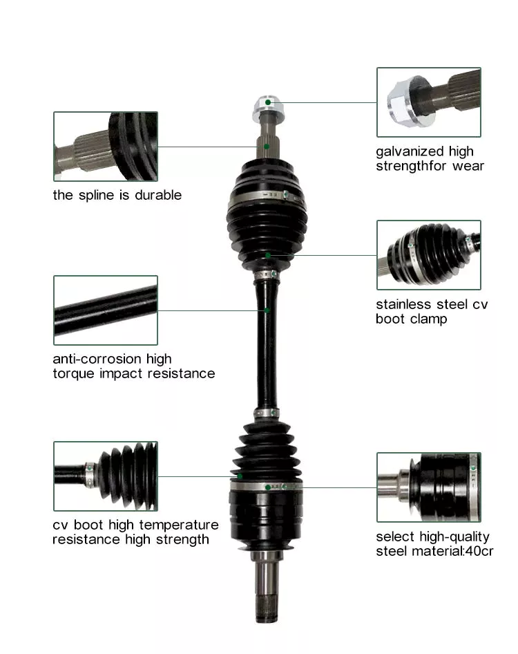
Can you explain the different types of PTO shafts and their applications?
PTO shafts (Power Take-Off shafts) come in various types, each designed for specific applications and requirements. The different types of PTO shafts offer versatility and compatibility with a wide range of machinery and implements. Here’s an explanation of the most common types of PTO shafts and their applications:
1. Standard PTO Shaft: The standard PTO shaft, also known as a splined shaft, is the most common type used in agricultural and industrial machinery. It consists of a solid steel shaft with splines or grooves along its length. The standard PTO shaft typically has six splines, although variations with four or eight splines can be found. This type of PTO shaft is widely used in tractors and various implements, including mowers, balers, tillers, and rotary cutters. The splines provide a secure connection between the power source and the driven machinery, ensuring efficient power transfer.
2. Shear Bolt PTO Shaft: Shear bolt PTO shafts are designed with a safety feature that allows the shaft to separate in case of overload or sudden shock to protect the driveline components. These PTO shafts incorporate a shear bolt mechanism that connects the tractor’s power take-off to the driven machinery. In the event of excessive load or sudden resistance, the shear bolt is designed to break, disconnecting the PTO shaft and preventing damage to the driveline. Shear bolt PTO shafts are commonly used in equipment that may encounter sudden obstructions or high-stress situations, such as wood chippers, stump grinders, and heavy-duty rotary cutters.
3. Friction Clutch PTO Shaft: Friction clutch PTO shafts feature a clutch mechanism that allows for smooth engagement and disengagement of the power transfer. These PTO shafts typically incorporate a friction disc and a pressure plate, similar to a traditional vehicle clutch system. The friction clutch allows operators to gradually engage or disengage the power transfer, reducing shock loads and minimizing wear on the driveline components. Friction clutch PTO shafts are commonly used in applications where precise control of power engagement is required, such as in hydraulic pumps, generators, and industrial mixers.
4. Constant Velocity (CV) PTO Shaft: Constant Velocity (CV) PTO shafts, also known as homokinetic shafts, are designed to accommodate high angles of misalignment without affecting power transmission. They use a universal joint mechanism that allows for smooth power transfer even when the driven machinery is at an angle relative to the power source. CV PTO shafts are frequently used in applications where the machinery requires a significant range of movement or articulation, such as in articulated loaders, telescopic handlers, and self-propelled sprayers.
5. Telescopic PTO Shaft: Telescopic PTO shafts are adjustable in length, allowing for flexibility in equipment configuration and varying distances between the power source and the driven machinery. They consist of two or more concentric shafts that slide within each other, providing the ability to extend or retract the PTO shaft as needed. Telescopic PTO shafts are commonly used in applications where the distance between the tractor’s power take-off and the implement varies, such as in front-mounted implements, snow blowers, and self-loading wagons. The telescopic design enables easy adaptation to different equipment setups and minimizes the risk of the PTO shaft dragging on the ground.
6. Gearbox PTO Shaft: Gearbox PTO shafts are designed to adapt power transmission between different rotational speeds or directions. They incorporate a gearbox mechanism that allows for speed reduction or increase, as well as the ability to change rotational direction. Gearbox PTO shafts are commonly used in applications where the driven machinery requires a different speed or rotational direction than the tractor’s power take-off. Examples include grain augers, feed mixers, and industrial equipment that requires specific speed ratios or reversing capabilities.
It’s important to note that the availability and specific applications of PTO shaft types may vary based on regional and industry-specific factors. Additionally, certain machinery or implements may require specialized or custom PTO shafts to meet specific requirements.
In summary, the different types of PTO shafts, such as standard, shear bolt, friction clutch, constant velocity (CV), telescopic, and gearbox shafts, offer versatility and compatibility with various machinery and implements. Each type of PTO shaft is designed to address specific needs, such as power transfer efficiency, safety, smooth engagement, misalignment tolerance, adaptability, and speed/direction adjustment. Understanding the different types of PTO shafts and their applications is crucial for selecting the appropriate shaft forthe intended machinery and ensuring optimal performance and reliability.

editor by CX 2024-04-22

























