
Opis produktu
OEM ODM Cardan Transmission Tractor Parts Plastic Sleeve Clutch Limiter Pto Drive Shaft for Agriculture Machinery
Opis produktu
The PTO drive shaft from HangZhou CZPT Industry Co., Ltd. is compatible with various brands of agricultural machinery, particularly tractors. It facilitates power transmission in modern agricultural equipment, commonly connecting tractors to implements or within the machinery itself for smooth operation. The shaft boasts universal transmission capabilities and adjustable structure for different models. Most of our OEM customers usually send their drawings, if you have special request, send us your drawing or send us sample it is also OK.
Key Features:
1. Suitable for various agricultural machinery brands
2. Facilitates power transmission in modern equipment
3. Enables normal operation of agricultural machinery
4. Universal transmission characteristics
5. Adjustable structure for different models
A power take-off (PTO) is a method of extracting power from an engine and transferring it to attached implements or separate machines. Our high-quality PTO shaft parts and accessories, including clutches, tubes, and yokes, cater to your tractor and implement needs, offering a wide range of PTO driveline products. Get our top-notch PTO shaft products at competitive rates.
PTO driveshaft:
| PTO DRIVE SHAFT T SERIES | |||||||
| Moment obrotowy roboczy | |||||||
| Szereg | 540 obrotów na minutę | 1000 obr./min | Poseł (NM) |
||||
| kW | Pakiet | Nm | kW | Pakiet | Nm | ||
| T1 | 12 | 16 | 210 | 18 | 25 | 172 | 320 |
| T2 | 15 | 21 | 270 | 23 | 31 | 220 | 450 |
| T2 | 22 | 30 | 390 | 35 | 47 | 330 | 640 |
| T4 | 26 | 35 | 460 | 40 | 55 | 380 | 780 |
| T5 | 35 | 47 | 620 | 54 | 74 | 520 | 1050 |
| T6 | 47 | 64 | 830 | 74 | 100 | 710 | 1450 |
| T7 | 55 | 75 | 970 | 87 | 118 | 830 | 1800 |
| T7N | 55 | 75 | 970 | 87 | 118 | 830 | 1800 |
| T8 | 70 | 95 | 1240 | 110 | 150 | 1050 | 2250 |
| T38 | 78 | 105 | 1380 | 123 | 166 | 1175 | 2500 |
| T9 | 88 | 120 | 1560 | 140 | 190 | 1340 | 2800 |
| T10 | 106 | 145 | 1905 | 170 | 230 | 1650 | 3500 |
| PTO DRIVE SHAFT L SERIES | |||||||
| Moment obrotowy roboczy | |||||||
| Szereg | 540tr/min | 1000 obr./min | Poseł (NM) |
||||
| kW | Pakiet | Nm | kW | Pakiet | Nm | ||
| L1 | 12 | 16 | 210 | 18 | 25 | 172 | 320 |
| L2 | 15 | 21 | 270 | 23 | 31 | 220 | 450 |
| L3 | 22 | 30 | 390 | 35 | 47 | 330 | 640 |
| L4 | 26 | 35 | 460 | 40 | 55 | 380 | 780 |
| L5 | 35 | 47 | 970 | 54 | 74 | 520 | 1050 |
| L6 | 47 | 64 | 830 | 74 | 100 | 710 | 1450 |
| L32 | 39 | 53 | 695 | 61 | 83 | 580 | 1200 |
| PTO DRIVE SHAFT S SERIES | |||||||
| Moment obrotowy roboczy | |||||||
| Szereg | 540tr/min | 1000 obr./min | Poseł (NM) |
||||
| kW | Pakiet | Nm | kW | Pakiet | Nm | ||
| S6 | 47 | 64 | 830 | 74 | 100 | 710 | 1450 |
| S7 | 55 | 75 | 970 | 87 | 118 | 830 | 1800 |
| S8 | 70 | 95 | 1240 | 110 | 150 | 1050 | 2250 |
| S38 | 78 | 105 | 1380 | 123 | 166 | 1175 | 2500 |
| S32 | 39 | 53 | 695 | 61 | 83 | 580 | 1200 |
| S36 | 66 | 90 | 1175 | 102 | 139 | 975 | 2000 |
| S9 | 88 | 120 | 1560 | 140 | 190 | 1340 | 2800 |
| S10 | 106 | 145 | 1905 | 170 | 230 | 1650 | 3500 |
| S42 | 79 | 107 | 1400 | 122 | 166 | 1175 | 2500 |
| S48 | 133 | 180 | 2390 | 205 | 277 | 1958 | 4200 |
| S50 | 119 | 162 | 2095 | 182 | 248 | 1740 | 3700 |
| PTO DRIVE SHAFT G SERIES | |||||||
| Moment obrotowy roboczy | |||||||
| Szereg | 540tr/min | 1000 obr./min | Poseł (NM) |
||||
| kW | Pakiet | Nm | kW | Pakiet | Nm | ||
| G2 | 15 | 21 | 270 | 23 | 31 | 220 | 450 |
| G4 | 26 | 35 | 460 | 40 | 55 | 380 | 780 |
| G5 | 35 | 47 | 620 | 54 | 74 | 520 | 1050 |
| G6 | 47 | 64 | 830 | 74 | 100 | 710 | 1450 |
| G7 | 55 | 75 | 970 | 87 | 118 | 830 | 1800 |
| G8 | 70 | 95 | 1240 | 110 | 150 | 1050 | 2250 |
| G38 | 78 | 105 | 1380 | 123 | 166 | 1175 | 2500 |
| G42 | 79 | 107 | 1400 | 122 | 166 | 1175 | 2500 |
| G50 | 119 | 162 | 2095 | 182 | 248 | 1740 | 3700 |
There are thousands of items and hard to list all here, please feel free to send us enquiry by e-mail and then you can get the technical details you want from us.
Yoke
| TRIANGULAR YOKE | ||||
| Szereg | A(mm) | B(mm) | C(mm) | D(mm) |
| 1.06 | 22 | 54 | 77 | 32.4 |
| 1.07 | 22 | 54 | 77 | 26.6 |
| 2.06 | 23.8 | 61.3 | 82 | 36.1 |
| 2.07 | 23.8 | 61.3 | 82 | 29 |
| 3.06 | 27 | 70 | 90 | 43.4 |
| 3.07 | 27 | 70 | 90 | 36.1 |
| 4.06 | 27 | 74.6 | 90 | 43.4 |
| 4.07 | 27 | 74.6 | 90 | 36.1 |
| 5.06 | 30.2 | 80 | 98 | 51.3 |
| 5.07 | 30.2 | 80 | 98 | 44.7 |
| 32.06 | 32 | 76 | 98 | 51.3 |
| 32.07 | 32 | 76 | 98 | 44.7 |
| 6.06 | 30.2 | 92 | 104 | 53.6 |
| 6.07 | 30.2 | 92 | 104 | 44.7 |
| 7.06 | 30.2 | 106.5 | 117 | 53.6 |
| 7.07 | 30.2 | 106.5 | 117 | 44.7 |
| 7N.06 | 35 | 94 | 106 | 53.6 |
| 7N.07 | 35 | 94 | 106 | 44.7 |
| 36.06 | 36 | 89 | 106 | 53.6 |
| 36.07 | 36 | 89 | 106 | 44.7 |
| 8.06 | 35 | 106.5 | 121 | 62.7 |
| 8.07 | 35 | 106.5 | 121 | 53.6 |
| 38.06 | 38 | 105.6 | 121 | 62.7 |
| 38.07 | 38 | 105.6 | 121 | 53.6 |
| 9.06 | 41 | 108 | 130 | 62.7 |
| 9.07 | 41 | 108 | 130 | 53.6 |
| 10.06 | 41 | 118 | 125 | 62.7 |
| 10.07 | 41 | 118 | 125 | 53.6 |
| LEMON YOKE | |||||
| Szereg | A(mm) | B(mm) | C(mm) | D(mm) | E(mm) |
| 1.06L | 22 | 54 | 77 | 30 | 39 |
| 1.07L | 22 | 54 | 23.7 | 30.8 | |
| 2.06L | 23.8 | 61.3 | 82 | 41.2 | 48 |
| 2.07L | 23.8 | 61.3 | 82 | 34.5 | 40.1 |
| 3.06L | 27 | 70 | 90 | 41.2 | 48 |
| 3.07L | 27 | 70 | 90 | 34.5 | 40.1 |
| 4.06L | 27 | 74.6 | 90 | 41.2 | 48 |
| 4.07L | 27 | 74.6 | 90 | 34.5 | 40.1 |
| 5.06L | 30.2 | 80 | 98 | 48 | 57.5 |
| 5.07L | 30.2 | 80 | 98 | 39.5 | 49 |
| 32.06L | 32 | 76 | 98 | 48 | 57.5 |
| 32.07L | 32 | 76 | 98 | 39.5 | 49 |
| 6.06L | 30.2 | 92 | 104 | 48 | 57.5 |
| 6.07L | 30.2 | 92 | 104 | 39.5 | 49 |
| 7N.06L | 35 | 94 | 106 | 48 | 57.5 |
| 7N.07L | 35 | 94 | 106 | 39.5 | 49 |
| 36.06L | 36 | 89 | 106 | 48 | 57.5 |
| 36.07L | 36 | 89 | 106 | 39.5 | 49 |
| STAR YOKE | ||||
| Szereg | A(mm) | B(mm) | C(mm) | D(mm) |
| 6.06ST | 30.2 | 92 | 104 | 56.8 |
| 6.07ST | 30.2 | 92 | 104 | 47.4 |
| 7.06ST | 30.2 | 106.5 | 117 | 56.8 |
| 7.07ST | 30.2 | 106.5 | 117 | 47.4 |
| 8.06ST | 35 | 106.5 | 121 | 56.8 |
| 8.07ST | 35 | 106.5 | 121 | 47.4 |
| 7N.06ST | 35 | 94 | 106 | 56.8 |
| 7N.07ST | 35 | 94 | 106 | 47.4 |
| 32.06ST | 32 | 76 | 98 | 56.8 |
| 32.07ST | 32 | 76 | 98 | 47.4 |
| 36.06ST | 36 | 89 | 106 | 56.8 |
| 36.07ST | 36 | 89 | 106 | 47.4 |
| 9.06ST | 108 | 130 | 67.5 | |
| 9.07ST | 41 | 108 | 130 | 56.8 |
| 10.06ST | 41 | 118 | 125 | 67.5 |
| 10.07ST | 41 | 118 | 125 | 56.8 |
| 42.06ST | 42 | 104.5 | 130 | 67.5 |
| 42.07ST | 42 | 104.5 | 130 | 56.8 |
| 50.06ST | 50 | 118 | 133 | 67.5 |
| 50.07ST | 50 | 118 | 133 | 56.8 |
There are thousands of items and hard to list all here, please feel free to send us enquiry by e-mail and then you can get the technical details you want from us.
Safty shield:
| SHIELD I | |||||
| Szereg | Tube(A) | Retainingcollar(B) | Color | ||
| Wewnętrzny | Zewnętrzny | Wewnętrzny | Zewnętrzny | ||
| 1 | 48.5 | 54 | 34 | 40 | BI:Black YI:Yellow |
| 2 | 61 | 66.5 | 40 | 47 | |
| 3-4 | 61 | 66.5 | 46 | 53 | |
| 5 | 75 | 81 | 54 | 62 | |
| 06-7-8 | 75 | 81 | 59.5 | 68.5 | |
| 42/48/50 | 90 | 96 | 69.5 | 81.5 | |
| SHIELD II | |||||
| Szereg | Tube(A) | Retainingcollar(B) | Color | ||
| Wewnętrzny | Zewnętrzny | Wewnętrzny | Zewnętrzny | ||
| 1 | 48.5 | 54 | 34 | 40 | BII:Black YII:Yellow YBII:Yellow+Black |
| 2 | 61 | 66.5 | 40 | 47 | |
| 3-4 | 6 | 66.5 | 46 | 53 | |
| 5 | 75 | 81 | 54 | 62 | |
| 06-7-8 | 75 | 81 | 59.5 | 68.5 | |
| 42/48/50 | 90 | 96 | 69.5 | 81.5 | |
| SHIELD III | |||||
| Szereg | Tube(A) | Retainingcollar(B) | Color | ||
| Wewnętrzny | Zewnętrzny | Wewnętrzny | Zewnętrzny | ||
| 1 | 48.5 | 54 | 34 | 40 | BIII:Black YIII:Yellow |
| 2 | 61 | 66.5 | 40 | 47 | |
| 3-4 | 61 | 66.5 | 46 | 53 | |
| 5 | 75 | 81 | 54 | 62 | |
| 06-7-8 | 75 | 81 | 59.5 | 68.5 | |
| 42/48/50 | 90 | 96 | 69.5 | 81.5 | |
| SHIELD WA | |||||||
| Szereg | Tube(A) | Retainingcollar(B) | Wide Angle Shield | Color | |||
| Wewnętrzny | Zewnętrzny | Wewnętrzny | Zewnętrzny | C | D | BWA:Black YWA:Yellow YBWA:Yellow+Black |
|
| 4 | 61 | 66.5 | 46 | 53 | 117 | 210 | |
| 6/32/36 | 75 | 81 | 59.5 | 68.5 | 123 | 225 | |
| 8 | 75 | 81 | 62.5 | 72.5 | 127 | 245 | |
→→→There are thousands of items and hard to list all here, please feel free to send us enquiry by e-mail and then you can get the technical details you want from us.
Opakowanie i wysyłka
Ocean Group Co., Ltd. is a professional group manufacturer of a full range of high-quality products including gearbox, gear, gear rack, chain, sprocket, V pulley, timing pulley, coupling, drive shaft, drop forged parts, CNC machined parts, agricultural parts and conveyor line parts. Most of CZPT Oem customers will send their drawings, some will send their sample. CZPT is pride in its capacity to develop products based on individual designs. The group’s global stature is reinforced by excelent products and commitment to post-sale service, earning esteemed reputation on the international market.
Ocean have extensive experience in serving customers from various regions, with our products being well-received in the American, European, South American, and Asian markets. Manufactured using modern computerized machinery, our products meet international quality standards and are designed for optimal performance.
With a focus on competitive pricing, timely delivery, responsive customer service, and comprehensive after-sales support, CZPT ensure customer satisfaction at every step. Our production processes adhere to ISO9001 standards, and CZPT are capable of designing and manufacturing non-standard products to meet specific customer requirements.
Quality and credibility are at the core of our business philosophy, and CZPT are committed to providing the best services and top-notch products to our customers. For more information or samples, please reach out to us, and CZPT guarantee a prompt response.
Często zadawane pytania
Najczęściej zadawane pytania:
Q1: Are you trading company or manufacturer ?
A: We are factory.
Q2: How long is your delivery time and shipment?
1.Sample Lead-times: generally 10 workdays.
2.Production Lead-times: 20-40 workdays after getting your deposit.
Q3. What is your terms of payment?
A: T/T 30% as deposit, and 70% before delivery.
Q4: What is your advantages?
1. Manufacturer,the most competitive price and good quality.
2. Perfect technical engineers give you the best support.
3. OEM is available.
4. Rich stock and quick delivery.
Q5. If you can’t find the product on our website,what do you next?
Please send us inquiry with product pictures and drawings by email or other ways and we’ll check.
/* May 10, 2571 16:49:51 */!function(){function d(e,r){var a,o={};try{e&&e.split(“,”).forEach(function(e,t){e&&(a=e.match(/(.*?):(.*)$/))&&1
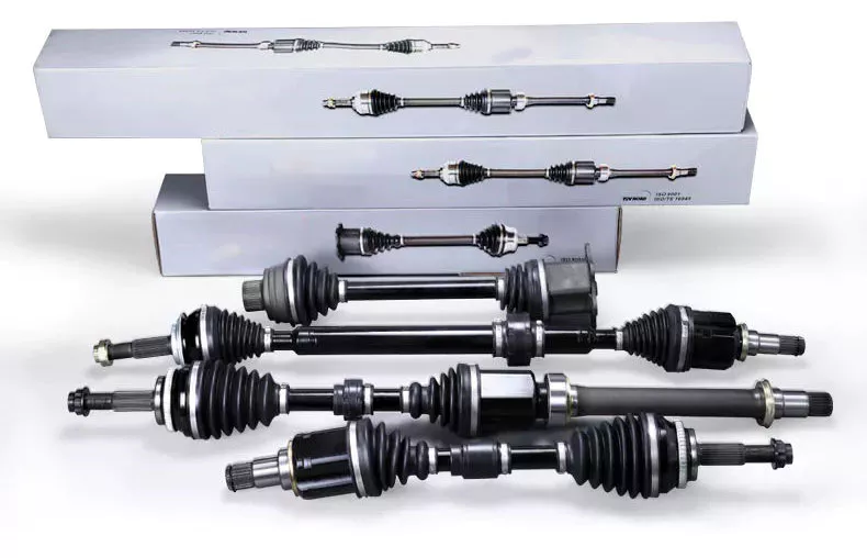
Can PTO drive shafts be adapted for use in both agricultural and industrial settings?
Yes, PTO (Power Take-Off) drive shafts can be adapted for use in both agricultural and industrial settings. While PTO drive shafts are commonly associated with agricultural machinery, their versatility and compatibility with various power-driven equipment make them suitable for industrial applications as well. Here’s a detailed explanation of how PTO drive shafts can be adapted for use in both agricultural and industrial settings:
1. Interchangeable Attachments:
PTO drive shafts are designed to accommodate different types of attachments or implements. In agricultural settings, these attachments can include rotary mowers, balers, tillers, and other farm equipment. Industrial applications may require PTO drive shafts for powering pumps, generators, compressors, or other machinery. The ability to interchange attachments allows PTO drive shafts to be used in a wide range of applications across both agricultural and industrial sectors.
2. Adjustable Lengths:
PTO drive shafts are often designed with adjustable lengths to accommodate different equipment setups. By adjusting the length, the drive shaft can be properly aligned and connected between the power source and the driven equipment, regardless of whether it is in an agricultural or industrial setting. This flexibility in length adjustment makes PTO drive shafts adaptable to various equipment configurations and ensures efficient power transfer in both sectors.
3. Power Compatibility:
PTO drive shafts are designed to transfer power from the power source (e.g., engine, motor) to the driven equipment. The power requirements in both agricultural and industrial settings can vary, but PTO drive shafts are built to handle a wide range of power outputs. The power compatibility of PTO drive shafts allows them to be used in different settings, whether it’s a tractor in a field or an industrial machine on a factory floor.
4. Zagadnienia bezpieczeństwa:
PTO drive shafts are engineered with safety in mind, irrespective of the setting in which they are used. Safety features such as shear pins, torque limiters, shielding, and guarding are incorporated into the design of PTO drive shafts to protect both operators and equipment. These safety considerations apply universally, ensuring that PTO drive shafts can be used safely in both agricultural and industrial environments.
5. Compliance with Standards:
PTO drive shafts are manufactured according to industry standards and regulations. These standards, such as ISO 500-1, specify requirements for power transmission components, including PTO drive shafts. Compliance with these standards ensures that the drive shafts meet necessary safety and performance criteria, regardless of the application. PTO drive shafts that meet industry standards can be confidently used in both agricultural and industrial settings.
6. Opcje personalizacji:
Manufacturers of PTO drive shafts often provide customization options to meet specific requirements. This allows customers in both agricultural and industrial sectors to tailor the drive shafts to their unique needs. Customization options can include different lengths, connection types, and protective features, ensuring that PTO drive shafts can be adapted to various applications in both sectors.
7. Maintenance and Compatibility:
The maintenance practices and compatibility requirements for PTO drive shafts are generally similar across agricultural and industrial settings. Regular maintenance, such as lubrication, inspection, and torque checks, is essential for prolonging the lifespan and ensuring optimal performance in both sectors. The fundamental principles of power transmission and safety apply to both agricultural and industrial settings, making the use of PTO drive shafts consistent across these sectors.
In conclusion, PTO drive shafts can be successfully adapted for use in both agricultural and industrial settings. Their interchangeable attachments, adjustable lengths, power compatibility, safety considerations, compliance with standards, customization options, and maintenance practices make them versatile and suitable for a wide range of applications in both sectors. Whether it’s powering agricultural machinery or industrial equipment, PTO drive shafts provide efficient power transfer and reliable performance.

What safety precautions should be followed when working with PTO drive shafts?
Working with PTO (Power Take-Off) drive shafts requires strict adherence to safety precautions to prevent accidents and ensure the well-being of individuals operating or maintaining the equipment. Here are some important safety precautions to follow when working with PTO drive shafts:
1. Read and Understand the Manufacturer’s Instructions:
Before working with PTO drive shafts, carefully read and understand the manufacturer’s instructions, operating manuals, and safety guidelines. Familiarize yourself with the specific requirements and recommendations for the PTO drive shaft model being used. The manufacturer’s instructions provide essential information regarding installation, operation, maintenance, and safety precautions.
2. Wear Appropriate Personal Protective Equipment (PPE):
Always wear the necessary personal protective equipment (PPE) when working with PTO drive shafts. This may include safety glasses, protective gloves, steel-toed boots, and appropriate clothing. PPE helps protect against potential hazards such as flying debris, entanglement, or contact with rotating components.
3. Ensure Proper Installation and Alignment:
Follow the recommended installation procedures for the PTO drive shaft. Ensure that it is correctly aligned and securely attached to both the power source and the driven equipment. Improper installation or misalignment can lead to excessive vibration, premature wear, and potential dislodgement of the drive shaft during operation.
4. Use Safety Guards and Shields:
PTO drive shafts should be equipped with appropriate safety guards and shields. These protective devices help prevent accidental contact with rotating components and minimize the risk of entanglement. Ensure that the guards and shields are properly installed and in good working condition. Do not remove or bypass them during operation.
5. Avoid Loose Clothing, Jewelry, and Hair:
When working with PTO drive shafts, avoid wearing loose clothing, jewelry, or having long hair that can get entangled in the rotating components. Secure or remove any loose items that could pose a risk of entanglement or become caught in the drive shaft during operation.
6. Disconnect Power Before Maintenance:
Prior to performing any maintenance or inspection on the PTO drive shaft, ensure that the power source is completely shut off and the equipment is at a complete stop. Disconnect the power supply and take appropriate measures to prevent accidental startup, such as locking out and tagging out the power source.
7. Regularly Inspect and Maintain the Drive Shaft:
Regularly inspect the PTO drive shaft for signs of wear, damage, or misalignment. Check for loose or missing components, and ensure that all fasteners and connections are secure. Lubricate the drive shaft as recommended by the manufacturer. Promptly address any maintenance or repair needs to prevent further damage or potential safety hazards.
8. Be Cautious of Overload and Shock Loads:
Avoid subjecting the PTO drive shaft to excessive loads or sudden shock loads beyond its rated capacity. Overloading can lead to premature wear, component failure, and potential accidents. Ensure that the equipment being driven by the PTO drive shaft does not exceed its recommended load limits.
9. Provide Training and Awareness:
Ensure that individuals working with or around PTO drive shafts receive proper training and are aware of the associated risks and safety precautions. Training should cover installation procedures, safe operation, maintenance practices, and emergency procedures. Promote a safety-conscious culture and encourage reporting of any safety concerns or incidents.
10. Seek Professional Assistance When Needed:
If you’re unsure about any aspect of working with PTO drive shafts or encounter complex maintenance or repair needs, seek professional assistance. Consulting with qualified technicians, engineers, or the equipment manufacturer can help ensure that the work is carried out safely and effectively.
Remember, safety should always be the top priority when working with PTO drive shafts. Following these precautions helps minimize the risk of accidents, injuries, and equipment damage. It is essential to stay vigilant, exercise caution, and comply with relevant safety regulations and standards.
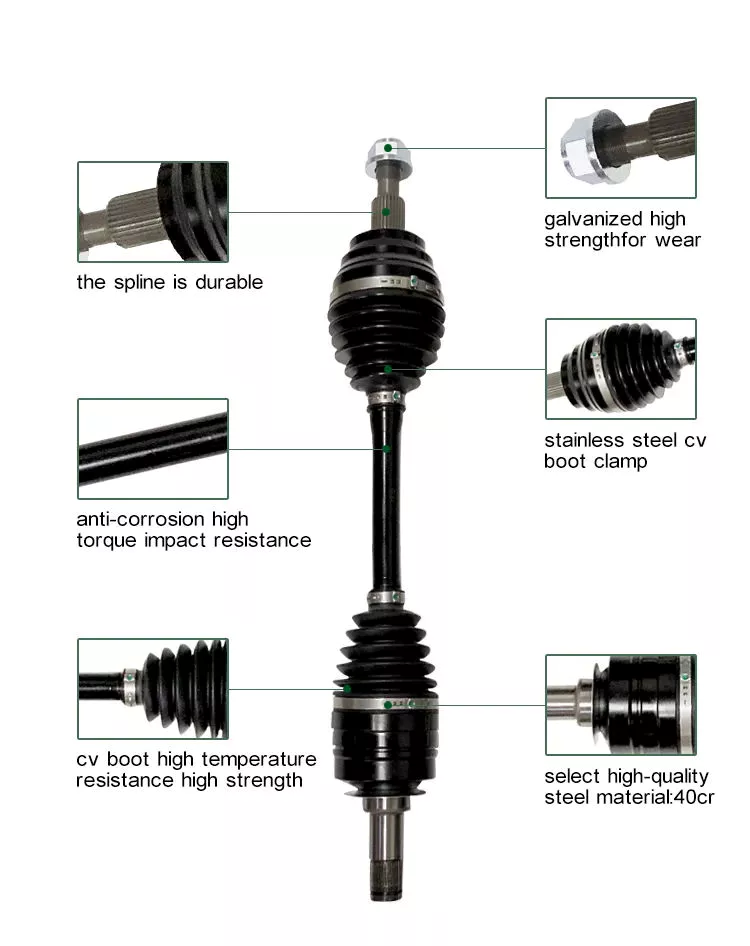
W jaki sposób wałki odbioru mocy radzą sobie ze zmianami prędkości, momentu obrotowego i kątów obrotu?
Wały napędowe WOM (WOM) zostały zaprojektowane tak, aby kompensować wahania prędkości, momentu obrotowego i kątów obrotu, umożliwiając efektywne przenoszenie mocy między głównym źródłem zasilania a narzędziem lub maszyną. Wahania te mogą wynikać z różnic w rozmiarach sprzętu, warunkach pracy i konkretnych wykonywanych zadaniach. Poniżej znajduje się szczegółowe wyjaśnienie, jak wały napędowe WOM radzą sobie z tymi wahaniami:
1. Zmiany prędkości:
Wały napędowe WOM są zaprojektowane tak, aby kompensować wahania prędkości między głównym źródłem napędu a narzędziem. Osiągają to dzięki połączeniu następujących czynników:
- Połączenia wielowypustowe: Wały napędowe WOM są wyposażone w połączenia wielowypustowe na obu końcach, co umożliwia bezpieczne i precyzyjne połączenie z wałem wyjściowym WOM i wałem wejściowym narzędzia. Te połączenia wielowypustowe zapewniają elastyczność w regulacji długości wału napędowego i dostosowaniu go do różnych wymagań prędkościowych.
- Mechanizm teleskopowy lub przesuwny: Niektóre wały napędowe WOM posiadają mechanizm teleskopowy lub przesuwny, który umożliwia regulację długości. Mechanizm ten umożliwia wałowi napędowemu dostosowywanie się do zmian prędkości poprzez jego wysuwanie lub wsuwanie, co pozwala na utrzymanie prawidłowego ustawienia i zapobiega nadmiernemu naprężeniu lub zakleszczeniu. Pozwala to na wydajną pracę wału napędowego nawet przy zmianie odległości między głównym źródłem zasilania a narzędziem.
- Kołki ścinające lub mechanizm sprzęgła: W sytuacjach nagłego wzrostu prędkości lub przeciążenia, wały napędowe WOM mogą być wyposażone w sworznie ścinane lub mechanizm sprzęgła. Te zabezpieczenia mają na celu odłączenie wału napędowego od głównego źródła zasilania, zapobiegając uszkodzeniu wału napędowego i współpracujących z nim urządzeń.
2. Zmiany momentu obrotowego:
Wały WOM są zbudowane tak, aby radzić sobie ze zmianami momentu obrotowego, które często występują podczas napędzania różnych typów maszyn i narzędzi. Oto jak radzą sobie ze zmianami momentu obrotowego:
- Połączenia wielowypustowe: Wielowypustowe połączenia wału napędowego i wału wyjściowego WOM zapewniają bezpieczne i solidne połączenie, które może przenosić wysoki moment obrotowy. Wielowypusty gwarantują prawidłowe ustawienie i przenoszenie momentu obrotowego między dwoma wałami, umożliwiając wałowi napędowemu dostosowanie się do zmiennego zapotrzebowania na moment obrotowy.
- Kołki ścinające lub mechanizm sprzęgła: Podobnie jak w przypadku zmian prędkości obrotowej, w wałach napędowych WOM można zastosować sworznie ścinane lub mechanizm sprzęgła, aby chronić je przed nadmiernym momentem obrotowym. W przypadku przeciążenia lub nagłego wzrostu momentu obrotowego, te zabezpieczenia odłączają wał napędowy od głównego źródła zasilania, zapobiegając uszkodzeniu wału napędowego i podłączonego sprzętu.
- Wzmocniona konstrukcja: Wały napędowe WOM są zazwyczaj wykonane z trwałych materiałów, takich jak stal lub stopy kompozytowe. Ta solidna konstrukcja pozwala im wytrzymywać wysokie poziomy momentu obrotowego i radzić sobie z wahaniami bez utraty integralności strukturalnej.
3. Kąty obrotu:
Wały napędowe WOM są zaprojektowane tak, aby kompensować różnice kątów obrotu między głównym źródłem zasilania a narzędziem. Oto jak sobie z nimi radzą:
- Elastyczna konstrukcja: Wały napędowe WOM są z natury elastyczne, co pozwala im dostosowywać się do różnych kątów obrotu. Wspomniane wcześniej połączenia wielowypustowe oraz mechanizmy teleskopowe lub przesuwne zapewniają niezbędną elastyczność, umożliwiającą obsługę zmian kąta bez negatywnego wpływu na przenoszenie mocy.
- Przeguby uniwersalne: W sytuacjach, w których występują znaczne wahania kątowe, wały napędowe WOM mogą być wyposażone w przeguby krzyżakowe. Przeguby krzyżakowe umożliwiają płynne przenoszenie mocy, nawet gdy wał wejściowy i wyjściowy są niewspółosiowe lub ustawione pod różnymi kątami. Dostosowują one zmiany kierunku obrotów i kompensują wahania kątowe, zapewniając efektywne przenoszenie mocy.
Dzięki zastosowaniu takich elementów jak połączenia wielowypustowe, mechanizmy teleskopowe lub przesuwne, sworznie ścinane lub mechanizmy sprzęgłowe, wzmocniona konstrukcja oraz przeguby uniwersalne, wały WOM radzą sobie ze zmianami prędkości, momentu obrotowego i kątów obrotu. Te elementy konstrukcyjne umożliwiają efektywne przenoszenie mocy i zapewniają płynną pracę narzędzi i maszyn w różnych zadaniach i warunkach pracy.


editor by lmc 2024-11-19

























