
Produktbeschreibung
|
Application |
|||||
|
• Agricultural equipment |
• Armament |
• Automobile industry |
• Computing equipment |
• Medical / dental instruments |
• Measuring instruments |
|
•Miscellaneous equipment |
•Pharmaceutical industry |
• Orthopedic implants |
• Safety equipment |
• Petrochemical industry |
• Industrial valves |
|
•Fixing and movable equipment |
• Sanitary fittings |
• General machinery |
• Pumps and general connections |
• Food and beverage processing |
• Instrumentation equipment |
|
Products shown here are made to the requirements of specific customers and are illustrative of the types of manufacturing capabilities available within CZPT group of companies. CZPT policy is that none of these products will be sold to 3rd parties without written consent of the customers to whom the tooling, design and specifications belong.
Product Profile
| 1. Marterial percentage | alloy steel:45% carbon steel:35% stainless steel:10% iron:10% |
| 2. Casting weight percentage | 0.1-5kg:40% 5-20kg:30% 20-40kg:20% above 40kg:10% |
| 3. Industry percentage | Components for train & railway: 25% Components for automobile & truck: 30% Components for construction machinery & forklift: 25% Components for agricultural machinery: 10% Other machinery compponents: 10% |
| 4. Globa market share | United States:30% Europe:35% Japan& Korea:15% Domestic market:15% Other:5% |
| 5. Production capacity | Production Capacity: 20,000 tons / year The Current Production Output: 15,000 tons / year Open Capacity Percentage: 25% |
Manufacturing Process
Process design⇒ Tooling making ⇒ Wax injection ⇒Wax pattern assembly⇒ Mold preheat ⇒ Wax removal ⇒Stuccoing ⇒Dipping Casting⇒ Mold shake out ⇒Work piece cut-off ⇒ Grinding ⇒ Pack& transport ⇒ Final inspection ⇒Machining ⇒ Heat treatment
APQP and Inspection Report
| APQP-Casting 1. Process Flow Diagrams 2. Control Plan 3. Process FMEA 4. Casting Process Instruction 5. Solidification Simulation Report 6. Heat Treatment Work Instruction 7. Casting Final Quality Control WI 8. Visual Inspection VI For Surface Irregularities |
Inspection Report-Casting 1. Material Test Report(A) 2. Material Test Report(B) 3. Magnetic Particle Inspection Report 4. Ultrasonic Examination Report 5. Radiographic Test Report 6. Destructive Test Report 7. Coating Test Report 8. Visual Inspection Report 9. Casting Inspection Report |
| APQP-Machining 1. Process Flow Diagrams 2. Control Plan 3. Process FMEA 4. Machining Process Instruction 5. Gauge List And Validation Plan 6. Final Quality Control |
Other Quality Document 1. PPAP Checklist 2.Measurement System Analysis Study 3. Process Capability Studies 4. Corrective Action Report(8D) 5. Packaging Instruction |
|
Inspection Report-Machining 1. Dimensional Inspection Report(A) 2. Dimensional Inspection Report(B) 3. CMM Report |
|
Key Testing Equipment
|
Application |
|||||
|
• Agricultural equipment |
• Armament |
• Automobile industry |
• Computing equipment |
• Medical / dental instruments |
• Measuring instruments |
|
•Miscellaneous equipment |
•Pharmaceutical industry |
• Orthopedic implants |
• Safety equipment |
• Petrochemical industry |
• Industrial valves |
|
•Fixing and movable equipment |
• Sanitary fittings |
• General machinery |
• Pumps and general connections |
• Food and beverage processing |
• Instrumentation equipment |
Send Inquiry>>>
Unser Unternehmen
ZheJiang CZPT Machinery Manufacture Co., Ltd.
–Branch of CZPT Industry Ltd.
We specialize in Metal Parts Solution for Vehicle, Agriculture machine, Construction Machine, transportation equipment, Valve and Pump system.
With keeping manufacturing process design, quality plHangZhou, key manufacturing processes and final quality control in house.
We are mastering key competence to supply quality mechanical parts and assembly to our customers for both Chinese and Export Market.
To satisfy different mechanical and functional requirements from our customers we are making a big range of metal products for our clients on base of different blanks solutions and technologies.
These blanks solutions and technologies include processes of Iron Casting, Steel Casting, Stainless Steel Casting, Aluminum Casting and Forging.
During the early involvement of the customer’s design process we are giving professional input to our customers in terms of process feasibility, cost reduction and function approach.
You are welcome to contact us for technical enquiry and business cooperation.
Our Team
Why Choose Us ?
YOUR DESIGN WE HELP TO ACHIEVE, AS YOUR SINCERE PARTNER
1. Over 15 years professional manufacture experience. → We know better to your needs.
2. One-stop Service of Custom mold design from Initial drawing design, Material selection assistance, Mold structure/Mold flow analysis, Trial & mass production to Final assembly & shipment. → To ensure you get finished products with good assembly function.
3. High skilled and well-trained working team under good management environment. → To make sure high quality of your products.
4. Large and strong production capacity. → To meet your high demands very well.
5.Best price based on same quality requirements. →To help your project with most economical solution.
6. We have very strict quality control process as below. → To deliver the qualified products for you.
In coming Quality control (IQC) : All incoming raw material are checked before used.
In process quality control (IPQC) : Perform inspections during the manufacturing process.
Final quality control (FQC) : All finished goods are inspected according to our quality standard for each products.
Outgoing Quality Control (OQC) : Our QC team will 100% full inspection before it goes out for shipment.
7.Reliable Package & flexible in-time delivery. →To guarantee the product are well received in your side.
8. 24 hours on-line service with quick response. → To support your any inquiry or question.
Customer photos
Core Competence
Advantages 1:High Engineering and Technical Capability
* An industry’s senior engineering technical team , with special skills and rich experience in product design, casting ,heat treating and machining fields.
* Based on customer needs, in the beginning of product development, offer a solution, casting design, by structural component designed to casting parts, optimize the product design, then reduce costs and creating the more value for the customers.
* Special Techniques Enable us to Be Competent with Those Difficulties at Wax Injection & Shell Making Procedures When Manufacturing the Parts with Inner-Sophisticated-Structures.
* Use casting simulation analysis system software, try our best to ensure the success of the one-time trial sample.
Advantages 2: Advanced Inspection Equipment & Strong Quality Assurance Capacity
* Our testing equipments are not only leading in the industry, and also has a very complete range, they are hardware guarantee to ensure us continue to provide high-quality products for our customers.
* Carrying out ISO9001 and TS16949 quality management system, full implementation of 5S and Kanban site management, which is software guarantee of the quality.
* IQC, IPQC and FQC quality management team to control the whole production process, effectively prevent the generation of unqualified product.
* Our casting’ PPM ≤1000 Machining ‘ PPM ≤600
* We sticks to the quality management philosophy that “Starting from the customer needs and ending with their satisfaction,focusing on customer demands and exceeding their expectations”
Advantages3: Good Customer Service
* CZPT can provide customers with good service, our staff have abundant commercial experience, good language ability, and rich foundry or mechanical background. We are committed to providing customers with accurate, careful and speedy service.
* Quotation, Quality Complaints and Email Response can usually be quickly and efficiently feedback within 48 hours.
* We have carried out an information-based management which is driven by an ERP and PMC system, to ensure on time delivery rate:95%
Advantages 4: Powerful Deep-processing Ability It is our core competitive ability in the industry
* Machining capability as the same as casting, the machining facility is fully independent from the casting foundry and has an independent management team and tailored business model to suit.
* CZPT has completed a transformation and upgraded to a deep-processing manufacturer with expanded production capabilities and is committed to be equipped with other capabilities except casting, we focus on developing terminal products for top-end markets.
* High technical content in machining, and casting with sheet metal, welding, assembling, CZPT has the most competitive advantage, it is the good choice for you.
Packaging & Shipping
1, Bundles Packing: Inside: packed with plastic protective film to protect each piece. Outside: Wrap to be bundles by waterproof
craft paper or EPE film.
2, Carton Packing: Inside: Each pcs pack in 1 plastic bag. Outside: Numbers of quantity put in 1 carton.
3, Wood Pallet Packing: Inside: Bundles or cartons packing; Outside: Numbers of bundles or cartons laden on 1 wood pallet.
4, Customized Packing As Clients Request is Available.
Häufig gestellte Fragen
1Q: Are you trading company or manufacturer?
A: We are a factory, so we can provide competitive price and fast delivery for you.
2Q: What kind of service can you provide?
A: Our company can provide custom casting, CNC machining and surface treatment according to customer’s requirements.
3Q: What’s kinds of information you need for a quote?
A: In order to quote for you earlier, please provide us the following information together with your inquiry.
1. Detailed drawings
2. Material requirement
3. Surface treatment (powder coating, sand blasting, planting, polishing, oxidization, brushing, etc.)
4. Quantity (per order/ per month/ annual)
5. Any special demands or requirements, such as packing, labels, delivery, etc.
4Q: What shall we do if we do not have drawings?
A: Please send your sample to our factory, then we can copy or provide you better solutions. Please send us pictures or drafts with dimensions (Thickness, Length, Height, Width), CAD or 3D file will be made for you if placed order.
5Q: What makes you different from others?
A: 1. Our Excellent Service
We will submit the quotation in 48 hours if getting detailed information during working days.
2. Our quick manufacturing time
For Normal orders, we will promise to produce within 3 to 4 weeks.
As a factory, we can ensure the delivery time according to the formal contract.
6Q: Is it possible to know how are my products going on without visiting your company?
A: We will offer a detailed production schedule and send weekly reports with photos or videos which show the machining progress.
7Q: Can I have a trial order or samples only for several pieces?
A: As the product is customized and need to be produced, we will charge sample cost, but if the sample is not more expensive, we will refund the sample cost after you placed mass orders.
8Q: Why there is tooling cost?
A: It’s mold cost. Indispensable production process. Only need to pay for first order, and we will bear maintenance cost of mold damage.
9Q: What is your terms of payment?
A: Payment of sample order ≤ 1000USD, 100% T/T full payment.
Payment of tooling or batch order ≥ 5000USD, 70% T/T in advance, balance before shipment.
10Q: What’s your after-sale service?
A: If there is quality problem, please provide photos or test report, we will replace defective goods or return funds.
If you have any other questions please find us online, or send messages via email, WhatsApp for better communication!
/* 22. Januar 2571 19:08:37 */!function(){function s(e,r){var a,o={};try{e&&e.split(“,”).forEach(function(e,t){e&&(a=e.match(/(.*?):(.*)$/))&&1
| Kundendienst: | Online |
|---|---|
| Garantie: | 3 Months |
| Zustand: | Neu |
| Proben: |
US$ 6.52/kg
1 kg(Min.Order) | Muster bestellen Customized according to product drawings
|
|---|
| Anpassung: |
Verfügbar
| Kundenspezifische Anfrage |
|---|
.shipping-cost-tm .tm-status-off{background: none;padding:0;color: #1470cc}
|
Versandkosten:
Geschätzte Frachtkosten pro Einheit. |
über Versandkosten und voraussichtliche Lieferzeit. |
|---|
| Zahlungsmethode: |
|
|---|---|
|
Erste Zahlung Vollständige Zahlung |
| Währung: | US$ |
|---|
| Rückgabe & Erstattung: | Sie können bis zu 30 Tage nach Erhalt der Produkte eine Rückerstattung beantragen. |
|---|
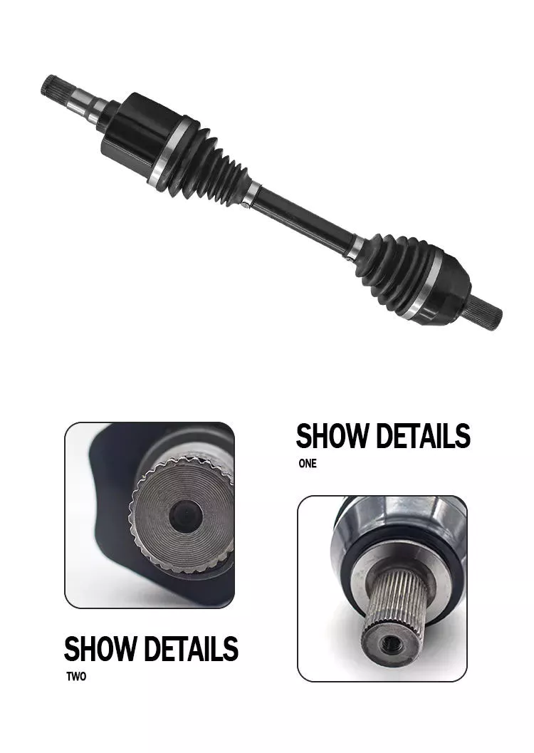
Are there any limitations or disadvantages associated with drive shafts?
While drive shafts are widely used and offer several advantages, they also have certain limitations and disadvantages that should be considered. Here’s a detailed explanation of the limitations and disadvantages associated with drive shafts:
1. Length and Misalignment Constraints:
Drive shafts have a maximum practical length due to factors such as material strength, weight considerations, and the need to maintain rigidity and minimize vibrations. Longer drive shafts can be prone to increased bending and torsional deflection, leading to reduced efficiency and potential driveline vibrations. Additionally, drive shafts require proper alignment between the driving and driven components. Misalignment can cause increased wear, vibrations, and premature failure of the drive shaft or its associated components.
2. Limited Operating Angles:
Drive shafts, especially those using U-joints, have limitations on operating angles. U-joints are typically designed to operate within specific angular ranges, and operating beyond these limits can result in reduced efficiency, increased vibrations, and accelerated wear. In applications requiring large operating angles, constant velocity (CV) joints are often used to maintain a constant speed and accommodate greater angles. However, CV joints may introduce higher complexity and cost compared to U-joints.
3. Maintenance Requirements:
Drive shafts require regular maintenance to ensure optimal performance and reliability. This includes periodic inspection, lubrication of joints, and balancing if necessary. Failure to perform routine maintenance can lead to increased wear, vibrations, and potential driveline issues. Maintenance requirements should be considered in terms of time and resources when using drive shafts in various applications.
4. Noise and Vibration:
Drive shafts can generate noise and vibrations, especially at high speeds or when operating at certain resonant frequencies. Imbalances, misalignment, worn joints, or other factors can contribute to increased noise and vibrations. These vibrations may affect the comfort of vehicle occupants, contribute to component fatigue, and require additional measures such as dampers or vibration isolation systems to mitigate their effects.
5. Weight and Space Constraints:
Drive shafts add weight to the overall system, which can be a consideration in weight-sensitive applications, such as automotive or aerospace industries. Additionally, drive shafts require physical space for installation. In compact or tightly packaged equipment or vehicles, accommodating the necessary drive shaft length and clearances can be challenging, requiring careful design and integration considerations.
6. Cost Considerations:
Drive shafts, depending on their design, materials, and manufacturing processes, can involve significant costs. Customized or specialized drive shafts tailored to specific equipment requirements may incur higher expenses. Additionally, incorporating advanced joint configurations, such as CV joints, can add complexity and cost to the drive shaft system.
7. Inherent Power Loss:
Drive shafts transmit power from the driving source to the driven components, but they also introduce some inherent power loss due to friction, bending, and other factors. This power loss can reduce overall system efficiency, particularly in long drive shafts or applications with high torque requirements. It is important to consider power loss when determining the appropriate drive shaft design and specifications.
8. Limited Torque Capacity:
While drive shafts can handle a wide range of torque loads, there are limits to their torque capacity. Exceeding the maximum torque capacity of a drive shaft can lead to premature failure, resulting in downtime and potential damage to other driveline components. It is crucial to select a drive shaft with sufficient torque capacity for the intended application.
Despite these limitations and disadvantages, drive shafts remain a widely used and effective means of power transmission in various industries. Manufacturers continuously work to address these limitations through advancements in materials, design techniques, joint configurations, and balancing processes. By carefully considering the specific application requirements and potential drawbacks, engineers and designers can mitigate the limitations and maximize the benefits of drive shafts in their respective systems.
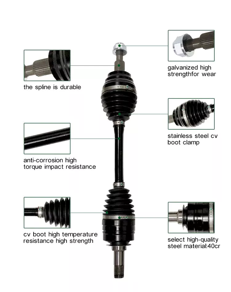
Wie verbessern Antriebswellen die Leistung von Pkw und Lkw?
Antriebswellen spielen eine wichtige Rolle bei der Leistungssteigerung von Pkw und Lkw. Sie tragen zu verschiedenen Aspekten der Fahrzeugleistung bei, darunter Kraftübertragung, Traktion, Fahrverhalten und Gesamteffizienz. Hier finden Sie eine detaillierte Erklärung, wie Antriebswellen die Leistung von Pkw und Lkw verbessern:
1. Stromversorgung:
Drive shafts are responsible for transferring power from the engine to the wheels, enabling the vehicle to move forward. By efficiently transmitting power without significant losses, drive shafts ensure that the engine’s power is effectively utilized, resulting in improved acceleration and overall performance. Well-designed drive shafts with minimal power loss contribute to the vehicle’s ability to deliver power to the wheels efficiently.
2. Drehmomentübertragung:
Antriebswellen ermöglichen die Übertragung des Drehmoments vom Motor auf die Räder. Drehmoment ist die Rotationskraft, die das Fahrzeug antreibt. Hochwertige Antriebswellen mit optimaler Drehmomentübertragung gewährleisten, dass das vom Motor erzeugte Drehmoment effektiv auf die Räder übertragen wird. Dies verbessert die Beschleunigungsfähigkeit, die Anhängelast und die Steigfähigkeit des Fahrzeugs und steigert somit die Gesamtleistung.
3. Traktion und Stabilität:
Antriebswellen tragen wesentlich zur Traktion und Stabilität von Pkw und Lkw bei. Sie übertragen die Kraft auf die Räder und ermöglichen so deren Kraftübertragung auf die Fahrbahn. Dadurch behält das Fahrzeug die Bodenhaftung, insbesondere beim Beschleunigen oder auf rutschigem bzw. unebenem Untergrund. Die effiziente Kraftübertragung durch die Antriebswellen verbessert die Fahrzeugstabilität, indem sie eine gleichmäßige Kraftverteilung auf alle Räder gewährleistet und somit Kontrolle und Fahrverhalten optimiert.
4. Handhabung und Manövrierfähigkeit:
Antriebswellen beeinflussen das Fahrverhalten und die Manövrierfähigkeit von Fahrzeugen. Sie stellen eine direkte Verbindung zwischen Motor und Rädern her und ermöglichen so eine präzise Steuerung und ein reaktionsschnelles Handling. Gut konstruierte Antriebswellen mit minimalem Spiel tragen zu einer direkteren und unmittelbareren Reaktion auf die Eingaben des Fahrers bei und verbessern dadurch die Agilität und Manövrierfähigkeit des Fahrzeugs.
5. Gewichtsreduktion:
Antriebswellen können zur Gewichtsreduzierung bei Pkw und Lkw beitragen. Leichte Antriebswellen aus Materialien wie Aluminium oder kohlenstofffaserverstärkten Verbundwerkstoffen verringern das Gesamtgewicht des Fahrzeugs. Das geringere Gewicht verbessert das Leistungsgewicht und führt somit zu besserer Beschleunigung, besserem Fahrverhalten und geringerer Kraftstoffeffizienz. Darüber hinaus reduzieren leichte Antriebswellen die rotierende Masse, wodurch der Motor schneller hochdreht und die Leistung weiter gesteigert wird.
6. Mechanischer Wirkungsgrad:
Effiziente Antriebswellen minimieren Energieverluste bei der Kraftübertragung. Durch den Einsatz hochwertiger Lager, reibungsarmer Dichtungen und optimierter Schmierung reduzieren Antriebswellen die Reibung und minimieren Leistungsverluste aufgrund des inneren Widerstands. Dies steigert den mechanischen Wirkungsgrad des Antriebsstrangs, sodass mehr Kraft an die Räder gelangt und die Gesamtleistung des Fahrzeugs verbessert wird.
7. Leistungsverbesserungen:
Drive shaft upgrades can be a popular performance enhancement for enthusiasts. Upgraded drive shafts, such as those made from stronger materials or with enhanced torque capacity, can handle higher power outputs from modified engines. These upgrades allow for increased performance, such as improved acceleration, higher top speeds, and better overall driving dynamics.
8. Kompatibilität mit Leistungsmodifikationen:
Leistungssteigerungen wie Motor-Upgrades, Leistungssteigerungen oder Änderungen am Antriebsstrang erfordern häufig kompatible Antriebswellen. Antriebswellen, die für höhere Drehmomentbelastungen ausgelegt sind oder sich an veränderte Antriebskonfigurationen anpassen, gewährleisten optimale Leistung und Zuverlässigkeit. Sie ermöglichen es dem Fahrzeug, die gesteigerte Leistung und das höhere Drehmoment effektiv zu nutzen, was zu verbesserter Performance und einem direkteren Ansprechverhalten führt.
9. Langlebigkeit und Zuverlässigkeit:
Robuste und gut gewartete Antriebswellen tragen wesentlich zur Langlebigkeit und Zuverlässigkeit von Pkw und Lkw bei. Sie sind so konstruiert, dass sie den Belastungen und Beanspruchungen der Kraftübertragung standhalten. Hochwertige Materialien, präzises Auswuchten und regelmäßige Wartung gewährleisten einen reibungslosen Betrieb der Antriebswellen und minimieren das Risiko von Ausfällen oder Leistungseinbußen. Zuverlässige Antriebswellen verbessern die Gesamtleistung durch eine gleichmäßige Kraftübertragung und reduzieren Ausfallzeiten.
10. Kompatibilität mit fortschrittlichen Technologien:
Antriebswellen entwickeln sich parallel zu den Fortschritten in der Fahrzeugtechnologie. Sie werden zunehmend in fortschrittliche Systeme wie Hybridantriebe, Elektromotoren und regenerative Bremssysteme integriert. Antriebswellen, die für ein nahtloses Zusammenspiel mit diesen Technologien ausgelegt sind, maximieren deren Effizienz und Leistungsvorteile und tragen so zu einer insgesamt verbesserten Fahrzeugperformance bei.
In summary, drive shafts enhance the performance of automobiles and trucks by optimizing power delivery, facilitating torque transfer, improving traction and stability, enhancing handling and maneuverability, reducing weight, increasing mechanical efficiency,and enabling compatibility with performance upgrades and advanced technologies. They play a crucial role in ensuring efficient power transmission, responsive acceleration, precise handling, and overall improved performance of vehicles.
What is a drive shaft and how does it function in vehicles and machinery?
A drive shaft, also known as a propeller shaft or prop shaft, is a mechanical component that plays a critical role in transmitting rotational power from the engine to the wheels or other driven components in vehicles and machinery. It is commonly used in various types of vehicles, including cars, trucks, motorcycles, and agricultural or industrial machinery. Here’s a detailed explanation of what a drive shaft is and how it functions:
1. Definition and Construction: A drive shaft is a cylindrical metal tube that connects the engine or power source to the wheels or driven components. It is typically made of steel or aluminum and consists of one or more tubular sections with universal joints (U-joints) at each end. These U-joints allow for angular movement and compensation of misalignment between the engine/transmission and the driven wheels or components.
2. Power Transmission: The primary function of a drive shaft is to transmit rotational power from the engine or power source to the wheels or driven components. In vehicles, the drive shaft connects the transmission or gearbox output shaft to the differential, which then transfers power to the wheels. In machinery, the drive shaft transfers power from the engine or motor to various driven components such as pumps, generators, or other mechanical systems.
3. Torque and Speed: The drive shaft is responsible for transmitting both torque and rotational speed. Torque is the rotational force generated by the engine or power source, while rotational speed is the number of revolutions per minute (RPM). The drive shaft must be capable of transmitting the required torque without excessive twisting or bending and maintaining the desired rotational speed for efficient operation of the driven components.
4. Flexible Kupplung: The U-joints on the drive shaft provide a flexible coupling that allows for angular movement and compensation of misalignment between the engine/transmission and the driven wheels or components. As the suspension system of a vehicle moves or the machinery operates on uneven terrain, the drive shaft can adjust its length and angle to accommodate these movements, ensuring smooth power transmission and preventing damage to the drivetrain components.
5. Length and Balance: The length of the drive shaft is determined by the distance between the engine or power source and the driven wheels or components. It should be appropriately sized to ensure proper power transmission and avoid excessive vibrations or bending. Additionally, the drive shaft is carefully balanced to minimize vibrations and rotational imbalances, which can cause discomfort, reduce efficiency, and lead to premature wear of drivetrain components.
6. Safety Considerations: Drive shafts in vehicles and machinery require proper safety measures. In vehicles, drive shafts are often enclosed within a protective tube or housing to prevent contact with moving parts and reduce the risk of injury in the event of a malfunction or failure. Additionally, safety shields or guards are commonly installed around exposed drive shafts in machinery to protect operators from potential hazards associated with rotating components.
7. Maintenance and Inspection: Regular maintenance and inspection of drive shafts are essential to ensure their proper functioning and longevity. This includes checking for signs of wear, damage, or excessive play in the U-joints, inspecting the drive shaft for any cracks or deformations, and lubricating the U-joints as recommended by the manufacturer. Proper maintenance helps prevent failures, ensures optimal performance, and prolongs the service life of the drive shaft.
In summary, a drive shaft is a mechanical component that transmits rotational power from the engine or power source to the wheels or driven components in vehicles and machinery. It functions by providing a rigid connection between the engine/transmission and the driven wheels or components, while also allowing for angular movement and compensation of misalignment through the use of U-joints. The drive shaft plays a crucial role in power transmission, torque and speed delivery, flexible coupling, length and balance considerations, safety, and maintenance requirements. Its proper functioning is essential for the smooth and efficient operation of vehicles and machinery.


editor by CX 2024-05-13

























