
Produktbeschreibung
Produktbeschreibung
SWC BH Cardan Shaft Basic Parameter And Main Dimension
Cardan shaft is widely used in rolling mill, punch, straightener, crusher, ship drive, paper making equipment, common machinery, water pump equipment, test bench, and other mechanical applications.
Advantage:
1. Low life-cycle costs and long service life;
2. Increase productivity;
3. Professional and innovative solutions;
4. Reduce carbon dioxide emissions, and environmental protection;
5. High torque capacity even at large deflection angles;
6. Easy to move and run smoothly;
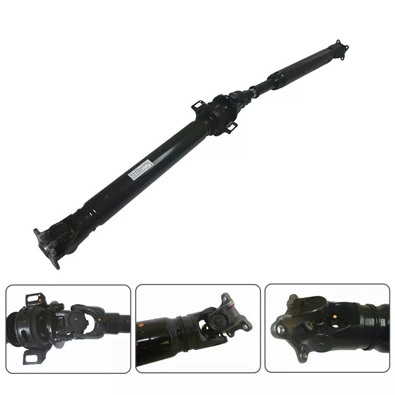
Detailed Photos
Product Parameters
| Modell | Tn kN • m |
T. |
p (.) |
LS mm |
Lmin | Size mm |
I kg. m2 | m kg |
|||||||||||
| Di js11 |
d2 H7 |
Da | Lm | n-d | k | t | b h9 |
g | Lmin | 100mm | Lmin | 100mm | |||||||
| SWC58BH | 58 | 0.15 | 0.075 | ≤22 | 35 | 325 | 47 | 30 | 38 | 35 | 4-5 | 3.5 | 1.5 | – | – | – | – | 2.2 | – |
| SWC65BH | 65 | 0.25 | 0.125 | ≤22 | 40 | 360 | 52 | 35 | 42 | 46 | 4-6 | 4.5 | 1.7 | – | – | – | – | 3.0 | – |
| SWC75BH | 75 | 0.50 | 0.25 | ≤22 | 40 | 395 | 62 | 42 | 50 | 58 | 6-6 | 5.5 | 2.0 | – | – | – | – | 5.0 | – |
| SWC90BH | 90 | 1.0 | 0.50 | ≤22 | 45 | 435 | 74.5 | 47 | 54 | 58 | 4-8 | 6.0 | 2.5 | – | – | – | – | 6.6 | – |
| SWC100BH | 100 | 1.5 | 0.75 | ≤25 | 55 | 390 | 84 | 57 | 60 | 58 | 6-9 | 7 | 2.5 | – | – | 0.0044 | 0.00019 | 6.1 | 0.35 |
| SWC120BH | 120 | 2.5 | 1.25 | ≤25 | 80 | 485 | 102 | 75 | 70 | 68 | 8-11 | 8 | 2.5 | – | – | 0.5719 | 0.00044 | 10.8 | 0.55 |
| SWC150BH | 150 | 5 | 2.5 | ≤25 | 80 | 590 | 13.0 | 90 | 89 | 80 | 8-13 | 10 | 3.0 | – | – | 0.0423 | 0.00157 | 24.5 | 0.85 |
| SWC160BH | 160 | 10 | 5 | ≤25 | 80 | 660 | 137 | 100 | 95 | 110 | 8-15 | 15 | 3.0 | 20 | 12 | 0.1450 | 0.0060 | 68 | 1.72 |
| SWC180BH | 180 | 20 | 10 | ≤25 | 100 | 810 | 155 | 105 | 114 | 130 | 8-17 | 17 | 5.0 | 24 | 14 | 0.1750 | 0.0070 | 70 | 2.8 |
| SWC200BH | 200 | 32 | 16 | ≤15 | 110 | 860 | 170 | 120 | 127 | 135 | 8-17 | 19 | 5.0 | 28 | 16 | 0.3100 | 0.0130 | 86 | 3.6 |
| SWC225BH | 225 | 40 | 20 | ≤15 | 140 | 920 | 196 | 135 | 152 | 120 | 8-17 | 20 | 5.0 | 32 | 9.0 | 0.5380 | 0.5714 | 122 | 4.9 |
| SWC250BH | 250 | 63 | 31.5 | ≤15 | 140 | 1035 | 218 | 150 | 168 | 140 | 8-19 | 25 | 6.0 | 40 | 12.5 | 0.9660 | 0.5717 | 172 | 5.3 |
| SWC285BH | 285 | 90 | 45 | ≤15 | 140 | 1190 | 245 | 170 | 194 | 160 | 8-21 | 27 | 7.0 | 40 | 15.0 | 2.0110 | 0.571 | 263 | 6.3 |
| SWC315BH | 315 | 125 | 63 | ≤15 | 140 | 1315 | 280 | 185 | 219 | 180 | 10-23 | 32 | 8.0 | 40 | 15.0 | 3.6050 | 0.571 | 382 | 8.0 |
| SWC350BH | 350 | 180 | 90 | ≤15 | 150 | 1410 | 310 | 210 | 267 | 194 | 10-23 | 35 | 8.0 | 50 | 16.0 | 7.571 | 0.2219 | 582 | 15.0 |
| SWC390BH | 390 | 250 | 125 | ≤15 | 170 | 1590 | 345 | 235 | 267 | 215 | 10-25 | 40 | 8.0 | 70 | 18.0 | 12.164 | 0.2219 | 738 | 15.0 |
| SWC440BH | 440 | 355 | 180 | ≤15 | 190 | 1875 | 390 | 255 | 325 | 260 | 16-28 | 42 | 10 | 80 | 20.0 | 21.420 | 0.4744 | 1190 | 21.7 |
| SWC490BH | 490 | 500 | 250 | ≤15 | 190 | 1985 | 435 | 275 | 325 | 270 | 16-31 | 47 | 12 | 90 | 22.5 | 32.860 | 0.4744 | 1452 | 21.7 |
| SWC550BH | 550 | 710 | 355 | ≤15 | 240 | 2300 | 492 | 320 | 426 | 305 | 16-31 | 50 | 12 | 100 | 22.5 | 68.920 | 1.3570 | 2380 | 34 |
Packaging & Shipping
Unternehmensprofil
HangZhou CZPT Machinery Manufacturing Co., Ltd. is a high-tech enterprise specializing in the design and manufacture of various types of coupling. There are 86 employees in our company, including 2 senior engineers and no fewer than 20 mechanical design and manufacture, heat treatment, welding, and other professionals.
Advanced and reasonable process, complete detection means. Our company actively introduces foreign advanced technology and equipment, on the basis of the condition, we make full use of the advantage and do more research and innovation. Strict to high quality and operate strictly in accordance with the ISO9000 quality certification system standard mode.
Our company supplies different kinds of products. High quality and reasonable price. We stick to the principle of “quality first, service first, continuous improvement and innovation to meet the customers” for the management and “zero defect, zero complaints” as the quality objective.
Unsere Dienstleistungen
1. Design Services
Our design team has experience in Cardan shafts relating to product design and development. If you have any needs for your new product or wish to make further improvements, we are here to offer our support.
2. Product Services
raw materials → Cutting → Forging →Rough machining →Shot blasting →Heat treatment →Testing →Fashioning →Cleaning→ Assembly→Packing→Shipping
3. Samples Procedure
We could develop the sample according to your requirement and amend the sample constantly to meet your need.
4. Research & Development
We usually research the new needs of the market and develop new models when there are new cars in the market.
5. Quality Control
Every step should be a particular test by Professional Staff according to the standard of ISO9001 and TS16949.
Häufig gestellte Fragen
Q 1: Are you a trading company or a manufacturer?
A: We are a professional manufacturer specializing in manufacturing
various series of couplings.
Q 2:Can you do OEM?
Yes, we can. We can do OEM & ODM for all customers with customized PDF or AI format artwork.
Q 3:How long is your delivery time?
Generally, it is 20-30 days if the goods are not in stock. It is according to quantity.
Q 4: Do you provide samples? Is it free or extra?
Yes, we could offer the sample but not for free. Actually, we have an excellent price principle, when you make the bulk order the cost of the sample will be deducted.
Q 5: How long is your warranty?
A: Our Warranty is 12 months under normal circumstances.
Q 6: What is the MOQ?
A: Usually our MOQ is 1pcs.
Q 7: Do you have inspection procedures for coupling?
A:100% self-inspection before packing.
Q 8: Can I have a visit to your factory before the order?
A: Sure, welcome to visit our factory.
Q 9: What’s your payment?
A:1) T/T.
♦Kontaktieren Sie uns
Web: huadingcoupling
Add: No.11 HangZhou Road,Chengnan park,HangZhou City,ZheJiang Province,China
/* 22. Januar 2571 19:08:37 */!function(){function s(e,r){var a,o={};try{e&&e.split(“,”).forEach(function(e,t){e&&(a=e.match(/(.*?):(.*)$/))&&1
| Standard Or Nonstandard: | Standard |
|---|---|
| Shaft Hole: | as Your Requirement |
| Torque: | as Your Requirement |
| Anpassung: |
Verfügbar
| Kundenspezifische Anfrage |
|---|
.shipping-cost-tm .tm-status-off{background: none;padding:0;color: #1470cc}
|
Versandkosten:
Geschätzte Frachtkosten pro Einheit. |
über Versandkosten und voraussichtliche Lieferzeit. |
|---|
| Zahlungsmethode: |
|
|---|---|
|
Erste Zahlung Vollständige Zahlung |
| Währung: | US$ |
|---|
| Rückgabe & Erstattung: | Sie können bis zu 30 Tage nach Erhalt der Produkte eine Rückerstattung beantragen. |
|---|

How do manufacturers ensure the compatibility of drive shafts with different equipment?
Manufacturers employ various strategies and processes to ensure the compatibility of drive shafts with different equipment. Compatibility refers to the ability of a drive shaft to effectively integrate and function within a specific piece of equipment or machinery. Manufacturers take into account several factors to ensure compatibility, including dimensional requirements, torque capacity, operating conditions, and specific application needs. Here’s a detailed explanation of how manufacturers ensure the compatibility of drive shafts:
1. Application Analysis:
Manufacturers begin by conducting a thorough analysis of the intended application and equipment requirements. This analysis involves understanding the specific torque and speed demands, operating conditions (such as temperature, vibration levels, and environmental factors), and any unique characteristics or constraints of the equipment. By gaining a comprehensive understanding of the application, manufacturers can tailor the design and specifications of the drive shaft to ensure compatibility.
2. Customization and Design:
Manufacturers often offer customization options to adapt drive shafts to different equipment. This customization involves tailoring the dimensions, materials, joint configurations, and other parameters to match the specific requirements of the equipment. By working closely with the equipment manufacturer or end-user, manufacturers can design drive shafts that align with the equipment’s mechanical interfaces, mounting points, available space, and other constraints. Customization ensures that the drive shaft fits seamlessly into the equipment, promoting compatibility and optimal performance.
3. Torque and Power Capacity:
Drive shaft manufacturers carefully determine the torque and power capacity of their products to ensure compatibility with different equipment. They consider factors such as the maximum torque requirements of the equipment, the expected operating conditions, and the safety margins necessary to withstand transient loads. By engineering drive shafts with appropriate torque ratings and power capacities, manufacturers ensure that the shaft can handle the demands of the equipment without experiencing premature failure or performance issues.
4. Material Selection:
Manufacturers choose materials for drive shafts based on the specific needs of different equipment. Factors such as torque capacity, operating temperature, corrosion resistance, and weight requirements influence material selection. Drive shafts may be made from various materials, including steel, aluminum alloys, or specialized composites, to provide the necessary strength, durability, and performance characteristics. The selected materials ensure compatibility with the equipment’s operating conditions, load requirements, and other environmental factors.
5. Joint Configurations:
Drive shafts incorporate joint configurations, such as universal joints (U-joints) or constant velocity (CV) joints, to accommodate different equipment needs. Manufacturers select and design the appropriate joint configuration based on factors such as operating angles, misalignment tolerances, and the desired level of smooth power transmission. The choice of joint configuration ensures that the drive shaft can effectively transmit power and accommodate the range of motion required by the equipment, promoting compatibility and reliable operation.
6. Quality Control and Testing:
Manufacturers implement stringent quality control processes and testing procedures to verify the compatibility of drive shafts with different equipment. These processes involve conducting dimensional inspections, material testing, torque and stress analysis, and performance testing under simulated operating conditions. By subjecting drive shafts to rigorous quality control measures, manufacturers can ensure that they meet the required specifications and performance criteria, guaranteeing compatibility with the intended equipment.
7. Einhaltung von Standards:
Manufacturers ensure that their drive shafts comply with relevant industry standards and regulations. Compliance with standards, such as ISO (International Organization for Standardization) or specific industry standards, provides assurance of quality, safety, and compatibility. Adhering to these standards helps manufacturers meet the expectations and requirements of equipment manufacturers and end-users, ensuring that the drive shafts are compatible and can be seamlessly integrated into different equipment.
8. Collaboration and Feedback:
Manufacturers often collaborate closely with equipment manufacturers, OEMs (Original Equipment Manufacturers), or end-users to gather feedback and incorporate their specific requirements into the drive shaft design and manufacturing processes. This collaborative approach ensures that the drive shafts are compatible with the intended equipment and meet the expectations of the end-users. By actively seeking input and feedback, manufacturers can continuously improve their products’ compatibility and performance.
In summary, manufacturers ensure the compatibility of drive shafts with different equipment through a combination of application analysis, customization, torque and power capacity considerations, material selection, joint configurations, quality control and testing, compliance with standards, and collaboration with equipment manufacturers and end-users. These efforts enable manufacturers to design and produce drive shafts that seamlessly integrate with various equipment, ensuring optimal performance, reliability, and compatibility in different applications.
Können Sie Beispiele aus der Praxis für Fahrzeuge und Maschinen nennen, die Antriebswellen verwenden?
Antriebswellen werden in verschiedenen Fahrzeugen und Maschinen eingesetzt, um die Kraft vom Motor oder der Energiequelle auf die Räder oder angetriebenen Bauteile zu übertragen. Hier einige Beispiele aus der Praxis: Fahrzeuge und Maschinen, die Antriebswellen verwenden:
1. Automobile:
Antriebswellen sind in Kraftfahrzeugen weit verbreitet, insbesondere in solchen mit Hinterrad- oder Allradantrieb. Bei diesen Fahrzeugen überträgt die Antriebswelle die Kraft vom Getriebe bzw. Verteilergetriebe zum Hinterachs- bzw. Vorderachsdifferenzial. Dadurch wird die Motorleistung auf die Räder verteilt und das Fahrzeug vorwärtsbewegt.
2. Lastwagen und Nutzfahrzeuge:
Antriebswellen sind wesentliche Bauteile von Lkw und Nutzfahrzeugen. Sie übertragen die Kraft vom Getriebe oder Verteilergetriebe auf die Hinterachse bzw. bei schweren Lkw auf mehrere Achsen. Antriebswellen in Nutzfahrzeugen sind für höhere Drehmomentbelastungen ausgelegt und oft größer und robuster als die in Pkw verwendeten.
3. Bau- und Erdbewegungsmaschinen:
Verschiedene Baumaschinen und Erdbewegungsgeräte wie Bagger, Lader, Planierraupen und Grader nutzen Antriebswellen zur Kraftübertragung. Diese Maschinen verfügen typischerweise über komplexe Antriebssysteme, die mithilfe von Antriebswellen die Kraft vom Motor auf die Räder oder Ketten übertragen und ihnen so den Einsatz bei schweren Aufgaben auf Baustellen oder im Bergbau ermöglichen.
4. Landwirtschaftliche Maschinen:
Landmaschinen wie Traktoren, Mähdrescher und Erntemaschinen nutzen Antriebswellen, um die Kraft vom Motor auf die Räder oder angetriebenen Bauteile zu übertragen. Antriebswellen in Landmaschinen sind oft hohen Belastungen ausgesetzt und können zusätzliche Merkmale wie Teleskopsegmente aufweisen, um unterschiedliche Abstände zwischen den Bauteilen auszugleichen.
5. Industriemaschinen:
Industriemaschinen wie Produktionsanlagen, Generatoren, Pumpen und Kompressoren verfügen häufig über Antriebswellen in ihren Kraftübertragungssystemen. Diese Antriebswellen übertragen die Kraft von Elektromotoren, Verbrennungsmotoren oder anderen Energiequellen auf verschiedene angetriebene Komponenten und ermöglichen es den Maschinen so, spezifische Aufgaben im industriellen Umfeld zu erfüllen.
6. Seeschiffe:
In der Schifffahrt werden Antriebswellen häufig eingesetzt, um die Kraft vom Motor auf den Propeller von Booten, Schiffen und anderen Wasserfahrzeugen zu übertragen. Schiffsantriebswellen sind typischerweise länger und so konstruiert, dass sie den besonderen Herausforderungen der Wasserumgebung standhalten, einschließlich Korrosionsbeständigkeit und geeigneter Dichtungsmechanismen.
7. Freizeitfahrzeuge (RVs) und Wohnmobile:
Wohnmobile und Reisemobile verwenden häufig Antriebswellen als Teil ihres Antriebssystems. Diese Antriebswellen übertragen die Kraft vom Getriebe auf die Hinterachse und ermöglichen so die Bewegung des Fahrzeugs. Antriebswellen in Wohnmobilen können zusätzliche Merkmale wie Dämpfer oder vibrationsdämpfende Komponenten aufweisen, um den Fahrkomfort zu erhöhen.
8. Geländefahrzeuge und Rennfahrzeuge:
Geländefahrzeuge wie SUVs, Pickups und Quads sowie Rennwagen verwenden häufig Antriebswellen. Diese Antriebswellen sind so konstruiert, dass sie den Belastungen im Gelände oder im Hochleistungsrennsport standhalten, die Kraft effizient auf die Räder übertragen und so optimale Traktion und Leistung gewährleisten.
9. Eisenbahn-Rollmaterial:
Im Eisenbahnwesen werden Antriebswellen in Lokomotiven und einigen Waggons eingesetzt. Sie übertragen die Kraft vom Lokomotivmotor auf die Räder bzw. das Antriebssystem und ermöglichen so die Fahrt des Zuges. Antriebswellen für Eisenbahnen sind typischerweise deutlich länger und können zusätzliche Merkmale aufweisen, um die Gelenk- oder Flexibilitätsbauweise mancher Zugkonfigurationen zu berücksichtigen.
10. Windkraftanlagen:
Großwindkraftanlagen zur Stromerzeugung nutzen Antriebswellen in ihren Kraftübertragungssystemen. Die Antriebswellen übertragen die Rotationsenergie der Turbinenblätter auf den Generator, wo sie in elektrische Energie umgewandelt wird. Die Antriebswellen von Windkraftanlagen sind so konstruiert, dass sie den hohen Drehmomenten und Rotationskräften des Windes standhalten.
Diese Beispiele verdeutlichen die breite Palette an Fahrzeugen und Maschinen, die für eine effiziente Kraftübertragung und den Antrieb auf Antriebswellen angewiesen sind. Antriebswellen sind in verschiedenen Branchen unverzichtbare Bauteile, die die Kraftübertragung von der Quelle zu den angetriebenen Komponenten ermöglichen und somit letztendlich Bewegung, Betrieb oder die Ausführung spezifischer Aufgaben ermöglichen.
Welche Vorteile bieten Antriebswellen für verschiedene Fahrzeug- und Gerätearten?
Antriebswellen bieten zahlreiche Vorteile für verschiedene Fahrzeug- und Gerätetypen. Sie spielen eine entscheidende Rolle bei der Kraftübertragung und tragen zur Gesamtleistung, Effizienz und Funktionalität verschiedener Systeme bei. Im Folgenden finden Sie eine detaillierte Erläuterung der Vorteile von Antriebswellen:
1. Effiziente Kraftübertragung:
Antriebswellen ermöglichen eine effiziente Kraftübertragung vom Motor bzw. der Antriebsquelle auf die Räder oder angetriebenen Komponenten. Durch die Verbindung von Motor und Antriebssystem übertragen sie die Rotationsenergie effizient und ermöglichen so den Betrieb von Fahrzeugen und Geräten. Diese effiziente Kraftübertragung gewährleistet die optimale Nutzung der vom Motor erzeugten Leistung und optimiert damit die Gesamtleistung und Produktivität des Systems.
2. Vielseitigkeit:
Antriebswellen sind vielseitig einsetzbar. Sie finden Verwendung in verschiedenen Fahrzeugtypen, darunter Pkw, Lkw, Motorräder und Geländewagen. Darüber hinaus werden Antriebswellen in einer Vielzahl von Geräten und Maschinen eingesetzt, beispielsweise in Landmaschinen, Baumaschinen, Industriemaschinen und Schiffen. Ihre Anpassungsfähigkeit an unterschiedliche Fahrzeug- und Gerätetypen macht Antriebswellen zu einer vielseitigen Komponente der Kraftübertragung.
3. Drehmomentbelastbarkeit:
Antriebswellen sind für hohe Drehmomente ausgelegt. Drehmoment ist die vom Motor oder der Antriebsquelle erzeugte Rotationskraft. Antriebswellen sind so konstruiert, dass sie dieses Drehmoment effizient und ohne übermäßige Verdrehung oder Biegung übertragen. Durch die effektive Drehmomentübertragung gewährleisten Antriebswellen, dass die vom Motor erzeugte Leistung zuverlässig auf die Räder oder angetriebenen Komponenten übertragen wird. Dadurch können Fahrzeuge und Geräte Widerstände wie schwere Lasten oder schwieriges Gelände überwinden.
4. Flexibilität und Vergütung:
Antriebswellen ermöglichen Flexibilität und gleichen Winkelbewegungen und Fluchtungsfehler aus. In Fahrzeugen gleichen sie die Bewegungen des Fahrwerks aus und ermöglichen so die unabhängige Auf- und Abwärtsbewegung der Räder. Diese Flexibilität gewährleistet eine konstante Kraftübertragung, selbst auf unebenem Gelände. Auch in Maschinen gleichen Antriebswellen Fluchtungsfehler zwischen Motor und angetriebenen Bauteilen aus, sorgen für eine gleichmäßige Kraftübertragung und verhindern übermäßige Belastungen des Antriebsstrangs.
5. Gewichtsreduktion:
Antriebswellen tragen zur Gewichtsreduzierung von Fahrzeugen und Geräten bei. Im Vergleich zu anderen Kraftübertragungsarten wie Riemen- oder Kettenantrieben sind Antriebswellen in der Regel leichter. Diese Gewichtsreduzierung verbessert den Kraftstoffverbrauch von Fahrzeugen und verringert das Gesamtgewicht der Geräte, was zu verbesserter Manövrierfähigkeit und höherer Nutzlast führt. Darüber hinaus tragen leichtere Antriebswellen zu einem besseren Leistungsgewicht bei, was wiederum die Fahrleistungen und die Beschleunigung verbessert.
6. Haltbarkeit und Langlebigkeit:
Antriebswellen sind auf Langlebigkeit und Robustheit ausgelegt. Sie werden aus Materialien wie Stahl oder Aluminium gefertigt, die hohe Festigkeit sowie Verschleiß- und Ermüdungsbeständigkeit bieten. Um ihre Zuverlässigkeit und Lebensdauer zu gewährleisten, werden Antriebswellen strengen Tests und Qualitätskontrollen unterzogen. Regelmäßige Wartung, einschließlich Schmierung und Inspektionen, trägt zusätzlich zur Langlebigkeit bei. Die robuste Konstruktion und die lange Lebensdauer von Antriebswellen tragen wesentlich zur Zuverlässigkeit und Wirtschaftlichkeit von Fahrzeugen und Maschinen bei.
7. Sicherheit:
Antriebswellen sind mit Sicherheitsmerkmalen ausgestattet, um Bediener und Umstehende zu schützen. In Fahrzeugen sind Antriebswellen häufig in einem Schutzrohr oder -gehäuse eingeschlossen, um den Kontakt mit beweglichen Teilen zu verhindern und das Verletzungsrisiko im Falle eines Defekts zu verringern. Auch in Maschinen werden üblicherweise Schutzabdeckungen oder Schutzvorrichtungen um freiliegende Antriebswellen angebracht, um die potenziellen Gefahren durch rotierende Bauteile zu minimieren. Diese Sicherheitsmaßnahmen gewährleisten die Sicherheit von Personen, die Fahrzeuge und Geräte bedienen oder in deren Nähe arbeiten.
Zusammenfassend bieten Antriebswellen zahlreiche Vorteile für verschiedene Fahrzeug- und Gerätearten. Sie ermöglichen eine effiziente Kraftübertragung, bieten vielseitige Einsatzmöglichkeiten, übertragen Drehmomente effektiv, bieten Flexibilität und Ausgleich, tragen zur Gewichtsreduzierung bei, gewährleisten Langlebigkeit und verfügen über Sicherheitsmerkmale. Durch diese Vorteile verbessern Antriebswellen die Leistung, Effizienz, Zuverlässigkeit und Sicherheit von Fahrzeugen und Geräten in einer Vielzahl von Branchen.


editor by CX 2024-05-07

























